14
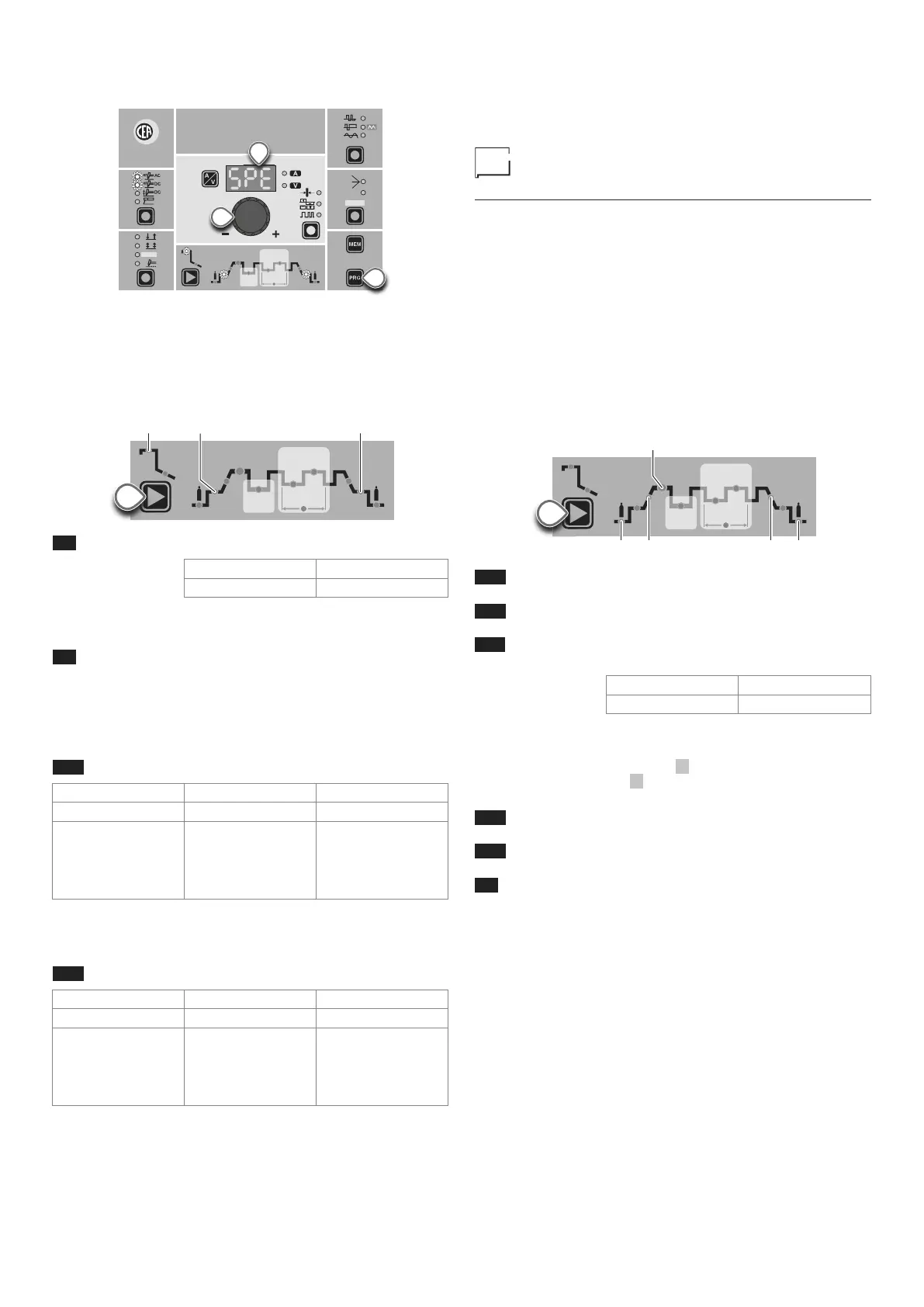
4) Turn the ENCODER Key (E) until the DISPLAY (D) shows
the following message: SPE (welder configured in SPECIAL
mode).
WAVE
ON
FAST
ULTRA
FAST
SLOW
SYN
CYCLE
HOT
START
ARC
FORCE
I2
PULSE
CYCLE
f
I
1
Ip
Ib
Ø
PULSE
E
T2
D
5) Press the “PRG” PROGRAM key (T2) to confirm.
The WELDING PARAMETERS included, that can be programmed
and changed (by turning the ENCODER knob) in the SPECIAL
(SPE) configuration, along with those in the STANDARD config-
uration, can be set by pushing the WELDING PARAMETER SE-
LECTION button (T10) successively:
HOT
START
ARC
FORCE
I2
PULSE
CYCLE
f
I
1
Ip
Ib
T10
L9 IGNITION CURRENT
4000 AC/DC 5000 AC/DC
5 ÷ 400 A 5 ÷ 500 A
WARNING: This can only be programmed for TIG AC with HF ig-
nition - TIG DC with HF ignition welding processes.
L9 IGNITION TIME duration (t.01 (0,01 sec) -
t.50 (0,50 sec))
WARNING: This can only be programmed when the TIG AC with
HF ignition welding process is active.
WARNING: If the value of these 2 parameters is too low, this could
prejudice ignition.
L16 IGNITION welding CURRENT
4000 AC/DC 5000 AC/DC
TIG DC 5 ÷ 400 A 5 ÷ 500 A
TIG AC
DYNAMIC TIG
SPEED TIG
COLD TIG
SOFT TIG
5 ÷ 400 A
5 ÷ 400 A
5 ÷ 231 A
5 ÷ 283 A
5 ÷ 500 A
5 ÷ 500 A
5 ÷ 289 A
5 ÷ 354 A
WARNING: This can only be programmed when the TIG AC with
HF ignition or TIG DC with HF ignition welding processes and
the 2 STROKES welding mode are used.
L20 FINAL welding CURRENT
4000 AC/DC 5000 AC/DC
TIG DC 5 ÷ 400 A 5 ÷ 500 A
TIG AC
DYNAMIC TIG
SPEED TIG
COLD TIG
SOFT TIG
5 ÷ 400 A
5 ÷ 400 A
5 ÷ 231 A
5 ÷ 283 A
5 ÷ 500 A
5 ÷ 500 A
5 ÷ 289 A
5 ÷ 354 A
WARNING: This can only be programmed when the TIG AC with
HF ignition or TIG DC with HF ignition welding processes and
the 2 STROKES welding mode are used.
To exit the setting phase, hold the WELDING PARAMETERS SE-
LECTION key (T10) down for about 1 second.
WARNING: These WELDING PARAMETERS are only to be acti-
vated by qualified personnel, or those trained by technicians.
Editing the maximum and minimum
limits for welding parameters
Welding machine in SPECIAL (SPE) configuration:
In welding processes:
• TIG AC with HF ignition
• TIG DC with HF ignition
The MATRIX AC/DC makes it possible to activate modification of
the MAXIMUM AND MINIMUM LIMITS for some WELDING PA-
RAMETERS thereby providing a more expert welder with a more
versatile welding machine.
Proceed as follows:
1) Switch on the welding machine by pushing and immediate-
ly releasing the WELDING PARAMETERS SELECTION Key
(T10).
2) Press the WELDING PARAMETERS SELECTION Key (T10)
a number of times to set the limits for the following welding
parameters:
HOT
START
ARC
FORCE
I2
PULSE
CYCLE
f
I
1
Ip
Ib
T10
L12 PRE-GAS duration (maximum limit settable from 1,00
to 2,50 sec)
L13 SLOPE UP duration (maximum limit settable from 5,00
to 10,0 sec)
L11 MINIMUM CURRENT for remote controls - minimum
limit settable:
4000 AC/DC 5000 AC/DC
5 ÷ 400 A 5 ÷ 500 A
WARNING: If the minimum limit setting (for the remote control
MINIMUM CURRENT) is greater than or equal to the value for the
PRINCIPAL welding CURRENT I1 , you will weld at the PRINCI-
PAL welding CURRENT I1 , irrespective of the setting you have
chosen for the remote control.
L14 SLOPE DOWN duration (maximum limit settable from
8,00 to 15,0 sec)
L15 POST-GAS duration (maximum limit settable from 10,0
to 25,0 sec)
L8 SPOT WELDING TIME (maximum limit settable from
10,0 to 25,0 sec)
To exit the setting phase, hold the WELDING PARAMETERS SE-
LECTION key (T10) down for about 1 second. The values set are
now active and welding can begin.