5
Instructions for use
COMMAND AND CONTROL UNITS (Fig. A)
Pos. 1 Welder cable.
Pos. 2 Power connector for cooling system.
Pos. 3 Weld gas inlet coupling.
Pos. 4 Supply switch. In the “O” position the welder is off.
Pos. 5 Fast coupling straight polarity.
Pos. 6 Fast coupling TIG torch gas tube.
Pos. 7 TIG weld auxiliary control connector (torch button, re-
mote control pedal, etc.).
Pos. 8 Fast coupling reverse polarity.
Pos. 9 MTA command and control panel.
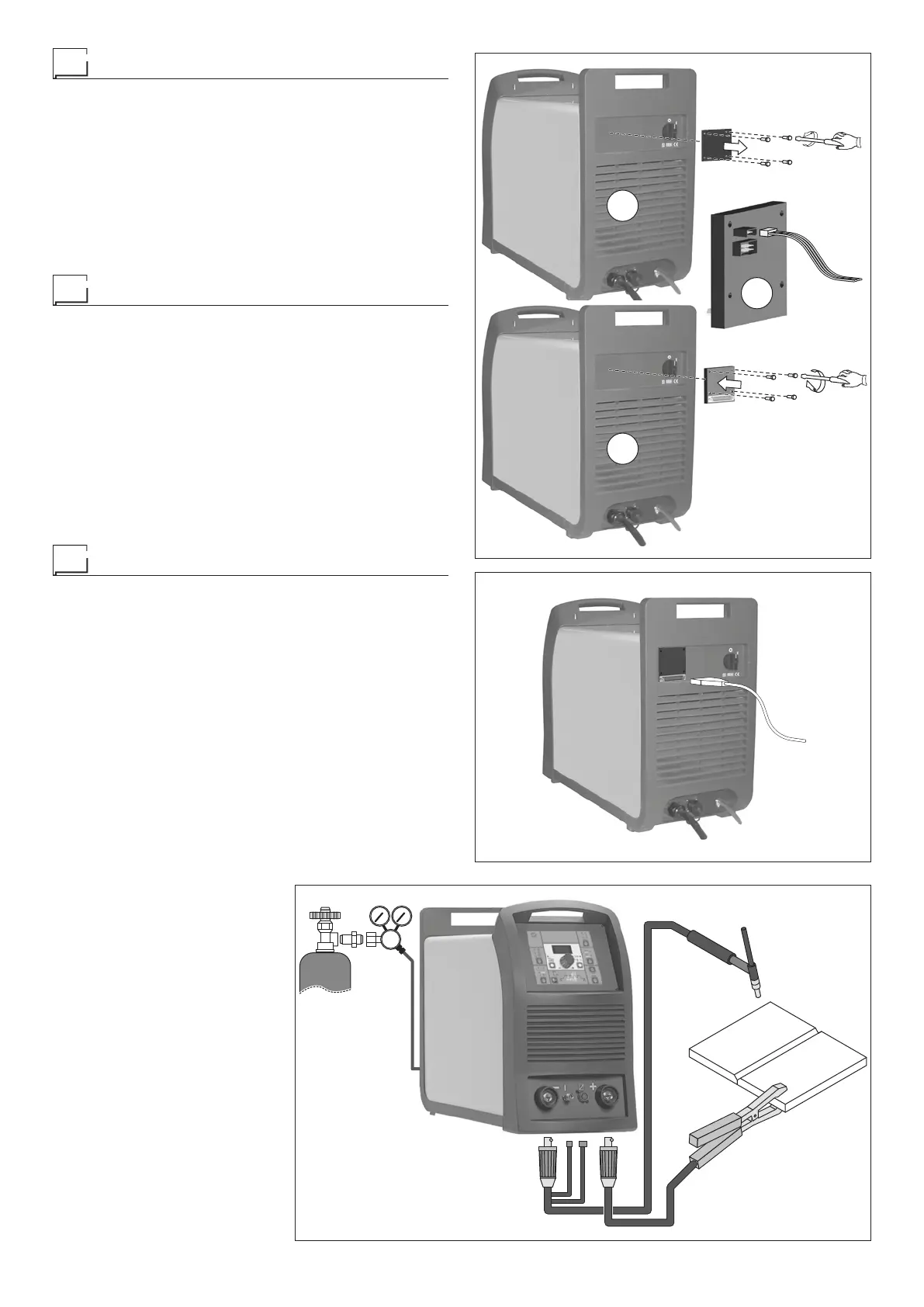
Interfacing accessories (optional)
Interface for RoboMAT 1 robot - Connection to welding ma-
chine:
1) Undo the 4 screws and remove the plate fixed to the rear
panel (Fig. B1).
2) Connect the robot wiring harness connector to the Robo-
MAT 1 robotic interface (Fig. B2).
3) Secure the RoboMAT 1 robotic interface to the rear pan-
el of the welding machine with the 4 supplied screws (Fig.
B3).
RoboMAT 1 robot - welding robot interface connecting ca-
ble - Connection to RoboMAT 1 robot interface:
1) Connect the cable to the robotic interface as indicated in
figure C. To connect the other end of this cable, see the di-
agramin the RoboMAT 1 robotic interface manual.
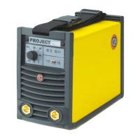
TIG welding
In the TIG process welding is achieved by melting the two metal
pieces to be joined, with the possible addition of material from
the outside, using an arc ignited by a tungsten electrode. The
molten bath and the electrode are protected by and inert gas
(for example, Argon). This type of welding is used to weld thin
sheet metal or when elevated quality is required.
1) Connecting the welding cables (Fig. D):
• Connect the gas hose to the Argon cylinder.
• With the machine switched off:
-
Connect the ground cable to the snap-on connector
marked + (positive).
-
Connect the relative ground clamp to the workpiece or
to the workpiece support in an area free of rust, paint,
grease, etc..
-
Connect the TIG torch power cable to the snap-on con
-
nector marked - (negative).
- Connect the torch gas tube to the connection (Pos. 6,
Fig. A).
- Insert the torch button connector in the 6 poles holder
(Pos. 7, Fig. A).
2) Switch the welding machine
on by moving the power sup-
ply switch to I (Pos. 4, Fig. A).
3) Make the adjustments and
select the parameters on the
control panel (for further infor-
mation see the MTA control
panel manual).
2
1
3
FIG. B
FIG. C
FIG. D
2000H810