2
ENGLISH
EN
Introduction 2
Control panel 2
Displaying the software version installed 5
Electrode welding (MMA) 5
TIG “AC” welding 6
TIG “DC” welding 8
TIG “AC and LIFT DC” welding with the SPOT
WELDING function on 9
TIG HF DC welding with TACK function active and
single ColdTack point 9
TIG HF DC welding with TACK function active and
Multi-ColdTack function 9
TIG “AC and DC” welding - Welding parameters 10
STANDARD CONFIGURATION (Std) 10
1 - “BASIC” WELDING PARAMETERS 10
2 - WELDING PARAMETERS with PULSE
mode active 10
3 - WELDING PARAMETERS with PULSE
mode and CYCLE welding mode active
(CYCLE LED on) 12
SPECIAL CONFIGURATION (SPE) 13
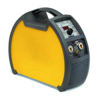
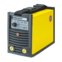
Introduction
This manual describes the functions on and how to use the fol-
lowing control panels:
• MTA 40
• MTA 50
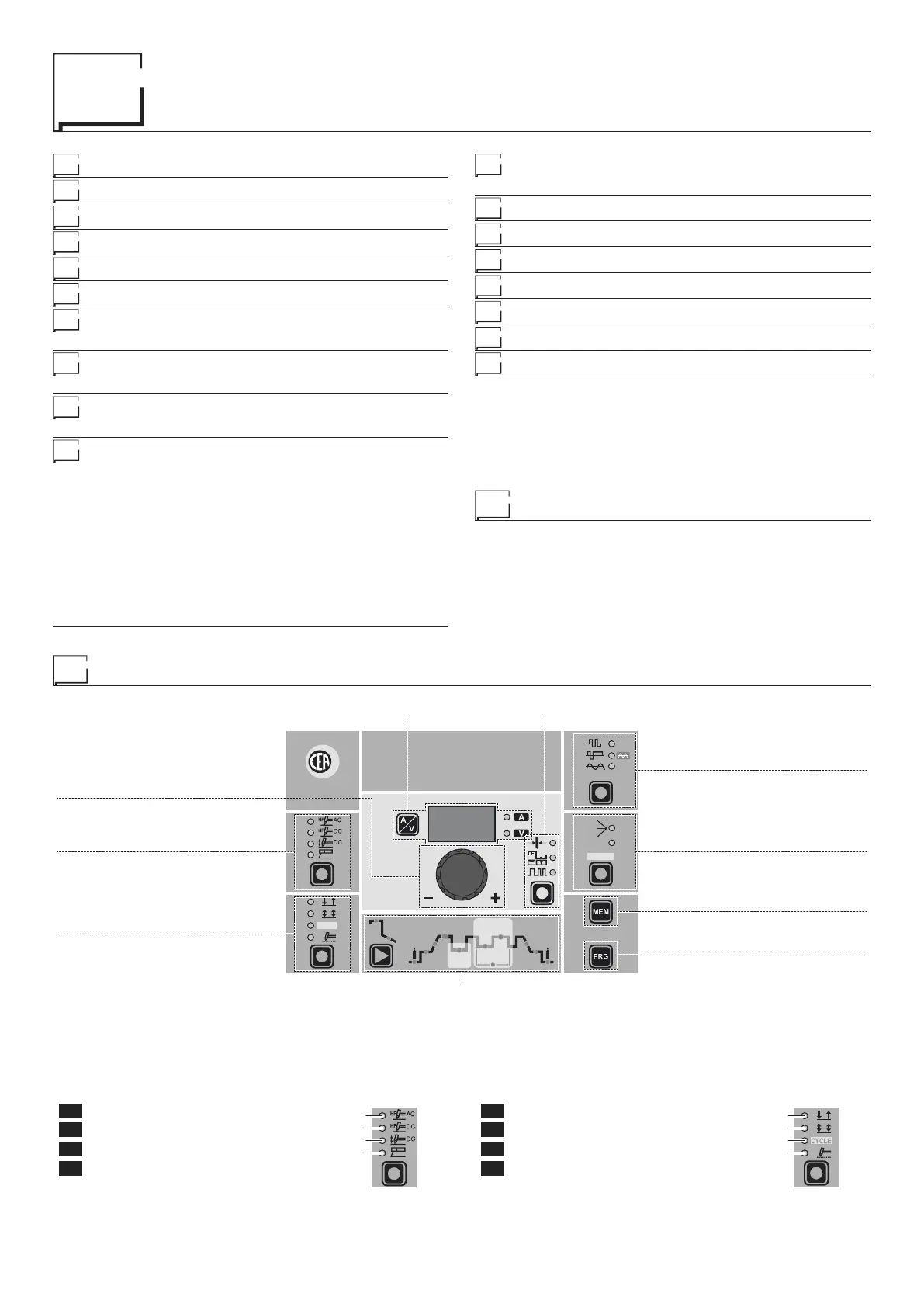
Control panel
■ WELDING PROCESS
The MATRIX welding machine offers 4 TIG/Electrode welding
processes. Each time the button is pushed, the welding machine
switches to select the welding process indicated by the LED that
stays lit, in the following order:
L1 TIG AC with HF ignition
L2 TIG DC with HF ignition
L3 TIG DC with “Lift” type ignition
L4 ELECTRODE (MMA)
L1
L2
L3
L4
■ WELDING MODE
The MATRIX welding machine offers 4 welding modes. Each time
the button is pushed, the welding machine switches to select the
welding mode indicated by the LED that stays lit, in the follow-
ing order:
L5 2 STROKES
L6 4 STROKES
L7 CYCLE
L8 SPOT WELDING
L5
L6
L7
L8
Editing the maximum and minimum limits for
welding parameters 14
Creating and memorising automatic welding points 15
PROGRAMMED and/or MANUAL welding 15
Calling up saved programs 15
Viewing the parameters set 16
Auxiliary functions 16
Factory default 16
Error and protection conditions 16
CYCLE
HOT
START
ARC
FORCE
I2
PULSE
CYCLE
f
I
1
Ip
Ib
WAVE
PULSE
ON
FAST
ULTRA
FAST
SLOW
SYN
Ø
WELDING PARAMETERS
ELECTRODE DIAMETER / BALANCING and FREQUENCYDISPLAY
ENCODER knob
WELDING PROCESS
WELDING MODE
WAVE
PULSE
SAVE “MEM”
PROGRAM “PRG”
 Loading...