3
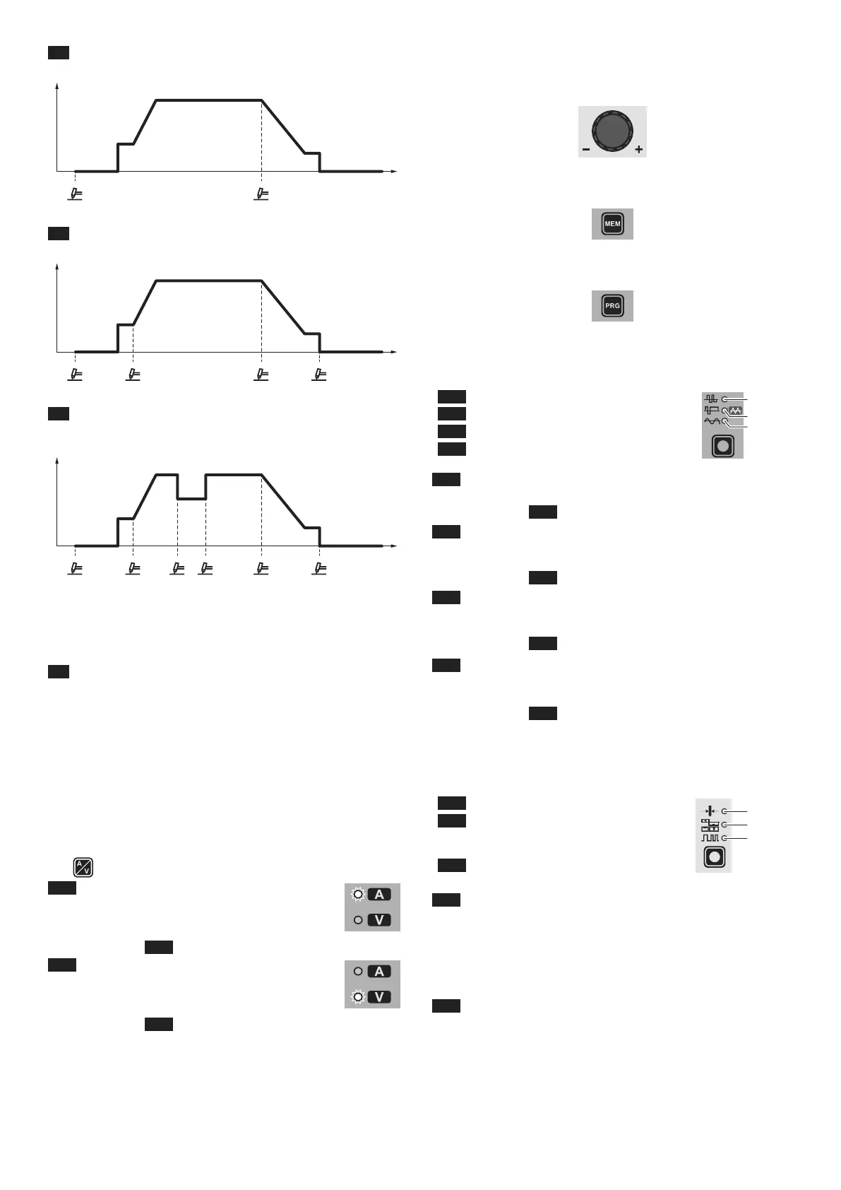
L5 2 STROKES
TIG welding takes place as follows:
WELDING CURRENT (I1)
I
1 (A)
POST GAS
2000HC22/A
t (sec)PRE-GAS
SLOPE UP
ON OFF
SLOPE DOWN
Initial Amps
Final Amps
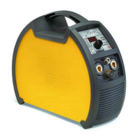
L6 4 STROKES
TIG welding takes place as follows:
WELDING CURRENT (I1)
I
1 (A)
POST GAS
2000HC22/A
t (sec)PRE-GAS
SLOPE UP
Initial Amps
SLOPE DOWN
Final Amps
ON ONOFF OFF
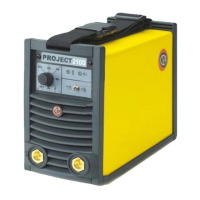
L7 CYCLE
When this function has been activated, TIG welding takes place
as follows:
WELDING CURRENT (I1)
WELDING
CURRENT (I
2)
I
1 (A)
POST GAS
2000HC22/A
t (sec)PRE-GAS
SLOPE UP
Initial Amps
SLOPE DOWN
Final Amps
ON ONOFF ON
OFF
ON
OFF
OFF
This welding mode is especially indicated for welding profiles with
different thickness, where continuous current variation is required.
Also, when welding aluminium, it allows you to have a higher initial
current, thereby facilitating pre-heating of the workpiece.
L8 SPOT WELDING
This can be used by pushing the torch button to spot weld for a pre-
set period of time (in seconds) at the end of which the arc switches
off automatically. The tack welding function is divided into 3 types:
• TIG AC and TIG LIFT DC tack welding.
• TIG HF DC tack welding with a single coldTack point.
• TIG HF DC tack welding with a Multi-ColdTack function.
See the relevant paragraphs in the subsequent pages of this man-
ual.
■ DISPLAY
Displays the selections made using the various Keys (with corre-
sponding LED on or flashing) and regulated using the ENCOD-
ER knob.
The
button can also be used to view:
L30 AMPERE (CURRENT )
•
When the machine is in stand-by, the Amps (A) set.
• When the machine is welding the real Amps (A) at
which the operator is actually welding.
WARNING: LED L30 switched on and steady.
L31 VOLT (VOLTAGE)
•
The actual VOLTS (V) at the welding clamps (the
value displayed CANNOT BE CHANGED OR
REGULATED).
WARNING: LED L31 switched on and steady.
■ ENCODER knob
This is used to regulate and change the welding parameters, ac-
cording to which LED is switched on and the value shown on the
DISPLAY, which is necessary for the machine to work correctly.
■ SAVE “MEM”
Used to save the parameters for the welding programs.
■ PROGRAM “PRG”
Used to call up welding programs.
■ WAVE
During TIG AC welding with HF ignition, it makes it possible to con-
trol the following wave shapes:
L22 DYNAMIC TIG
L23 SPEED TIG
L23 COLD TIG
L24 SOFT TIG
WAVE
L22 DYNAMIC TIG
Square wave: highly dynamic arc for all applications.
WARNING: LED L22 switched on and steady.
L23 SPEED TIG
Mixed wave: excellent penetration with high welding speed and
low electrode consumption.
WARNING: LED L23 switched on and steady.
L23 COLD TIG
Triangular wave: low heat generation with reduced distortion, ide-
al for minor thicknesses.
WARNING: LED L23 switched on and flashing.
L24 SOFT TIG
Sinusoidal wave: gentle, soft arc with low noise, ideal for aver-
age thicknesses.
WARNING: LED L24 switched on and steady.
■ ELECTRODE DIAMETER / BALANCING and
FREQUENCY
During TIG welding with HF ignition, it makes it possible to set one
of the following parameters, using the relevant key:
L27 ELECTRODE DIAMETER
L28 BALANCING of the TIME and
AMPLITUDE of the AC welding
current (BALANCE PLUS)
L29 FREQUENCY of the AC welding
current
Ø
L27
L28
L29
L27 ELECTRODE DIAMETER
For TIG welding with HF ignition, it allows you to use the relevant
key to set the diameter of the tungsten electrode used, and/or to
change it using the ENCODER knob, in order to achieve the best
control of the arc in a synergic manner.
WARNING: The electrode diameter CANNOT be selected when
the welding machine is set for the SPECIAL configuration.
L28 BALANCING of the TIME and AMPLITUDE of the AC
welding current (BALANCE PLUS)
It is possible to adjust both the time (t) and the amplitude of the
current (I) independently or simultaneously, using positive or neg-
ative values for the time the electrode stays in place. These set-
tings ensure perfect control of penetration and cleanliness, with a
drastic reduction in side incisions.