© CEDES | V 2.2 21
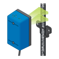
The downstream processing unit can detect floors and compensate for building shrinkage by recognizing the position
of each position indicator clip. This may require specific mounting positions. Consult the system integrator‘s installation
manual for further information on the positioning of the position indicator clips.
Important: The clip can only be reliably detected if the elevator travels not faster than ±0.3 m/s (depending on the
protocol up to 1 m/s, please refer to the Safety Manual).
7. Electrical connection
7.1 Interface from the APS sensor to the downstream processing unit
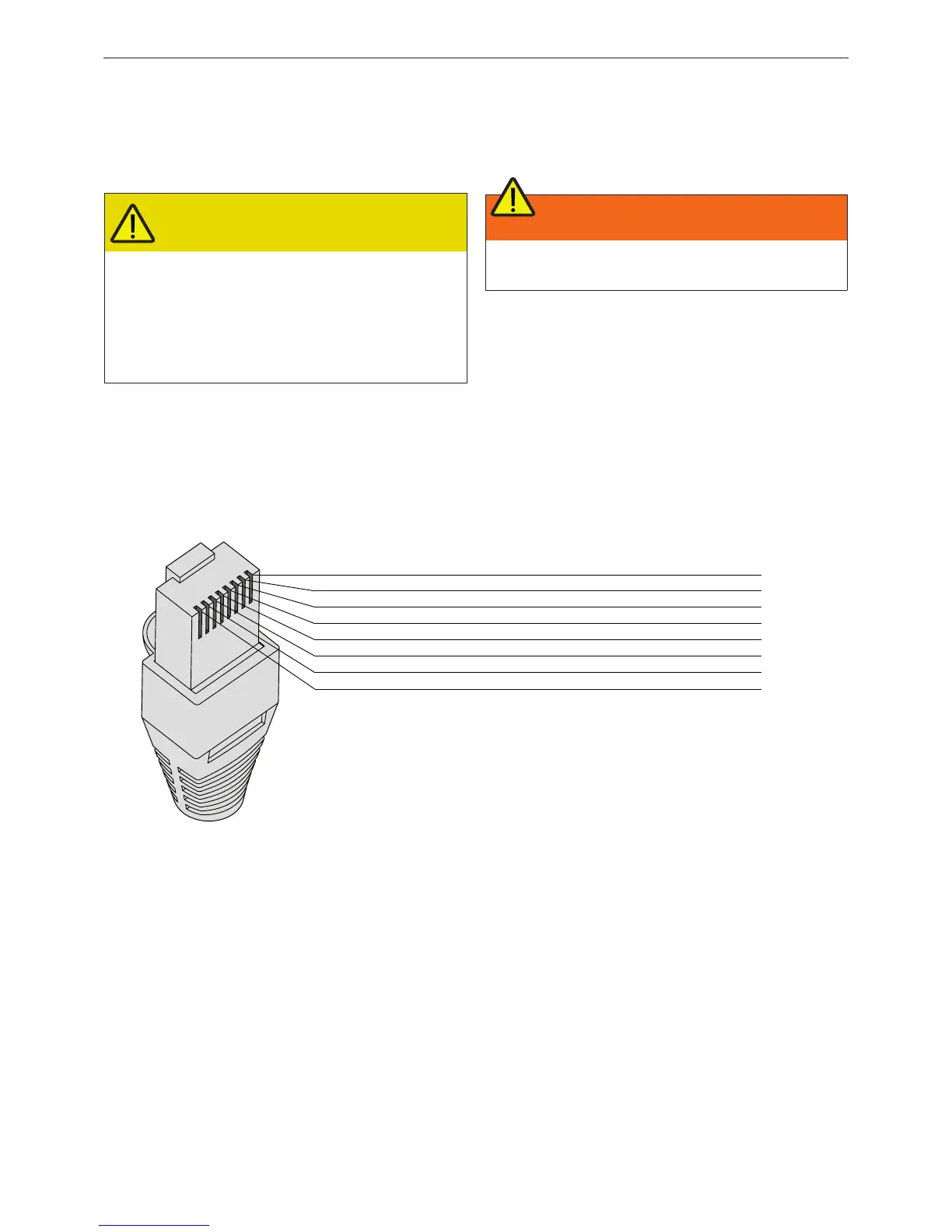
The APS sensor is connected to the downstream processing unit via an RJ45 connector. For detailed pin assignment
(Figure 46).
Figure 46: Pin assignment to RJ45 connector (CAN and RS485 interface)
For technical details, refer to the APS Safety Manual. It is the system integrator’s and electrical installer’s responsibility
to ensure that the cable is installed according to all national and local regulations (e.g. installation in a raceway as
required by Clause 38-021 in the Canadian Electrical Code Part 1).
CAUTION
Possible health risks
Where floor/door zone detection with the
position indicator clips is required, it must be
ensured that the clips have the same offset
on each floor relative to the landing door
sills. It is therefore important that the usage
of such functions is defined by the system
integrator.
WARNING
The installer has to strictly follow the system
intergrator’s instructions
12345678
8 yellow
7 brown
6 pink
5 black
4 white
3 green
2 grey
1 blue
CAN interface RS485 interface
CAN Channel 2 HIGH
CAN Channel 2 LOW
No function
No function
U
SP
GND
CAN Channel 1 HIGH
CAN Channel 1 LOW
GND_SEC*
No function
No function
No function
U
SP
GND
RS485 Channel 1 B
RS485 Channel 1 A
* GND_SEC is the isolated ground
of the RS485 transceiver