20 © CEDES | V 2.2
Table 6: Alignment indication from the sensor to the code tape and vice versa (at 105 mm distance between APS sensor and code tape)
Alignment Alignment LEDs Alignment Alignment LEDs
Left (-) /
right (+)
Signaling Limits LED [mm]
Near (-) /
far (+)
Signaling Limits LED
Cannot read
tape
Out of reading range
Cannot read
tape
Out of reading range
Too left
Out of
reading range
to -11.0
Too near
Out of
reading range
to -13.0
Slightly left
-11.0 to -4.0
Slightly too
near
-13.0 to -7.0
Position OK
-4.0 to +4.0
Position OK
-7.0 to +7.0
Slightly right
+4.0 to +11.0
Slightly too
far away
+7.0 to +13.0
Too right
+11.0 to
Out of
reading range
Too far away
+13.0 to
Out of
reading range
Cannot read
tape
Out of reading range
Cannot read
tape
Out of reading range
6.4 Clip installation and adjustment of
the APS system
The clips serve the following functions:
• Guideclip:
- Guides/aligns the code tape along the optical axis of
the APS sensor.
- Prevents the code tape from swinging and twisting.
• Positionindicatorclip:
- Guides/aligns the code tape along the optical axis of
the APS sensor.
- Prevents the code tape from swinging and twisting.
Depending on the downstream processing unit, the
APS sensor can detect the exact position of the position
indicator clip. The downstream processing unit can use
this information
- to detect doors and floors.
- to compensate for building shrinkage.
6.4.1 Installation of the guide clip
1. Whenever handling the code tape, use cut protection
gloves to prevent potential injury.
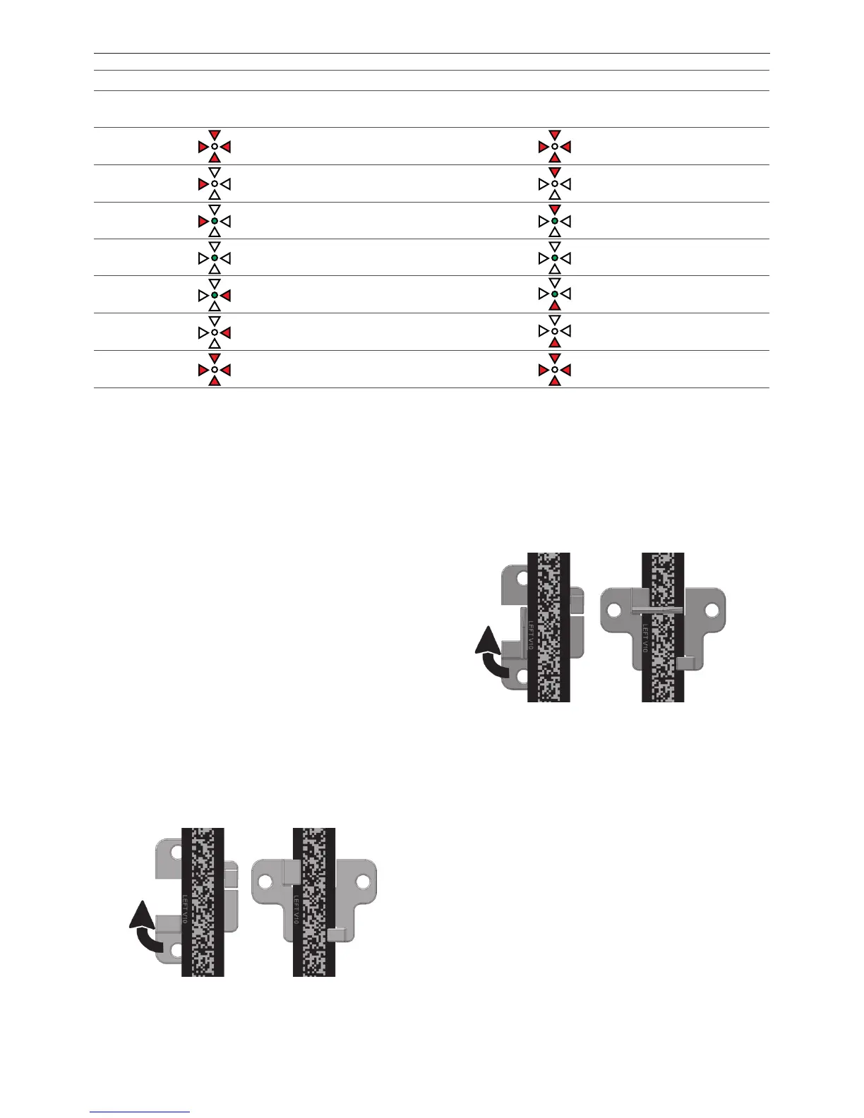
2. Insert the code tape into the clip guide rails (Figure
44).
Figure 44: Guide clip is inserted (left) and turned 90º clockwise
3. Turn the clip by 90º.
4. Fix the clip using appropriate screws and ring washer.
6.4.2 Installation of the position indicator
clip
1. For all operations with the code tape use cut
protection gloves to prevent of cutting.
2. Insert code tape in the clip guide rails (Figure 45).
Figure 45: APS position indicator clip is inserted (left) and turned
90º clockwise
3. Turn the clip by 90º.
4. Fix the clip using appropriate screws and ring washer.
5. The recommended distance between the clips
depends on the nominal speed of the elevator and
other factors such as airflow in the elevator shaft. A
typical value is 3 - 5 m. It is important that enough
clips are used to prevent the code tape from twisting.
Note: The limits are approximate values, they differ slightly from sensor to sensor (±0.5 mm).