© CEDES | V 2.2 7
5.3 Intended use
The APS is designed and approved for the use in elevator applications according to EN81-1/-2, EN81-20/50 and
ASME A17.1 and A17.5.
Three SIL 3 safety relevant functions are provided:
1. To safely detect the sensor‘s absolute position relative to the code tape (2 independent position values).
2. To safely calculate the velocity of the sensor compared to the code tape (2 independent velocity values).
3. Safely transmit the acquired values.
The two positions and velocities are derived by two independent channels; therefore the APS fulfills the requirements of
ASME A17.1 (2.25.2.xx and 2.25.4.xx).
For SIL safety, the APS must only be used for the SIL listed functions. If the APS is used in other applications or for other
functions, safety is not guaranteed. For more details refer to the APS Safety Manual.
5.4 System segregation
The safety of the whole system is the responsibility of the system integrator. For safety-relevant use, the system integrator
must only use the APS for the application as defined in the safety manual and according the instructions given herein.
The manufacturers of the each of the following, system, controller and drive, together with the installer, the operator and
those responsible for its maintenance have to follow the system integrator‘s instructions. Only personnel authorized and
instructed by the system integrator are allowed to operate, install and maintain the APS system.
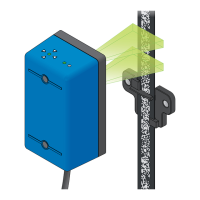
5.5 APS sensor
The APS sensor contains a dual camera system to determin the position of the elevator car. When the code tape is
illuminated by short infrared pulses, the APS sensor records the pattern in front of the cameras. Based on that data, the
sensor’s processor then calculates the position and velocity of the elevator car and crosschecks the results for increased
reliability. This data (one set of position and velocity values per camera) is transmitted to the downstream processing
unit via two separate CAN interfaces, one for each camera, or one RS485 interface.
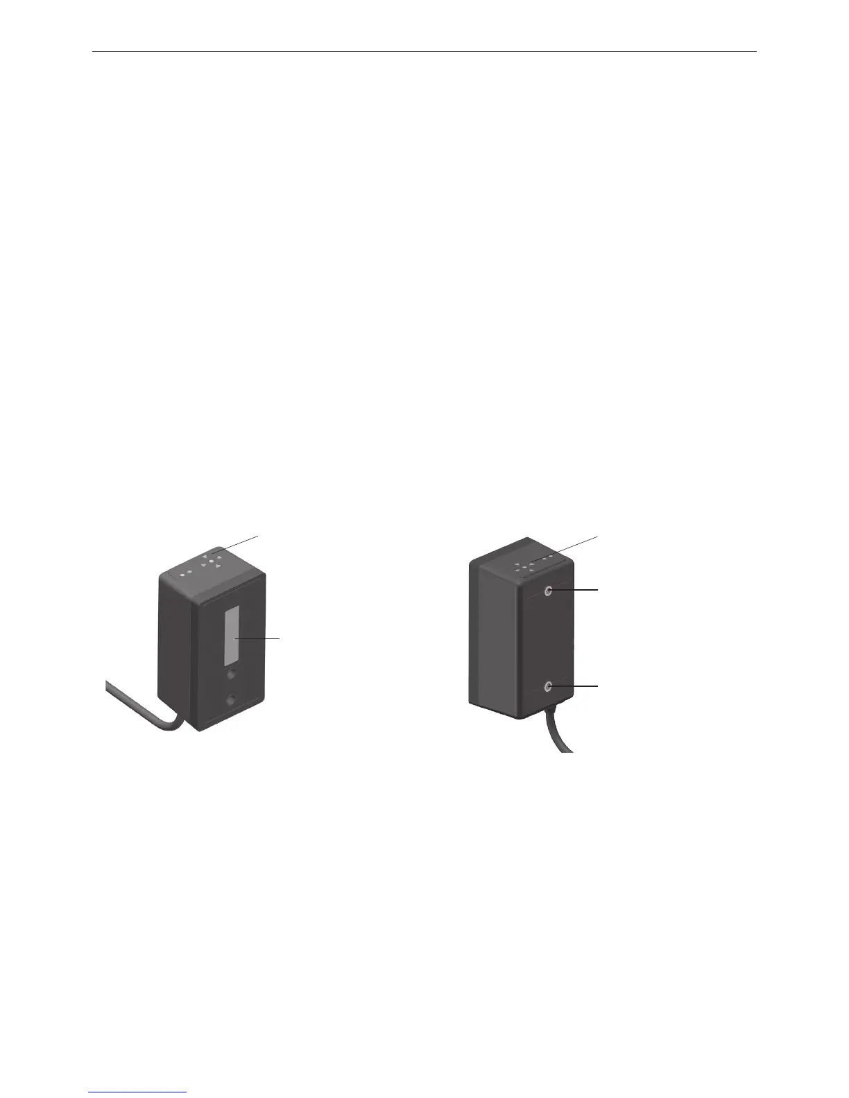
Figure 6: APS sensor (front side)
5.5.1 Interface from the APS sensor to the downstream processing unit
The interface of the APS sensor uses a CAN protocol (independent channel for each camera) / RS485 protocol (one
channel for both cameras) and is connected to the downstream processing unit through an RJ45 connector. For
technical details and data protocol, refer to the APS Safety Manual.
Figure 7: APS sensor (back side)
Indicator LED
Camera window
Indicator LED
Mounting press nut
M5x10
Mounting press nut
M5x10
Indicator LED
Mounting press nut
M5x10
(UNC 10-24)
Mounting press nut
M5x10
(UNC 10-24)