ENGLISH
20
Installation and control elements
• CEDIMA
®
• Technical Documentation • All rights reserved as per ISO 16016 • Subject to modications due to progressive development •
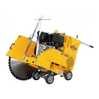
4.2.8 Adjusting the push rods
1. Loosen the counter nuts and the clamping screws at
the push rods (tubes, g. 4.7).
2. Pull out the push rods and adjust the inclination of
the rods in such a way that you can move the joint
cutter in a favourable posture.
3. Fix the push rods with the screws and counter nuts
shown on g. 4.7.
CF-2116 D adjustment of push rods Fig. 4.7
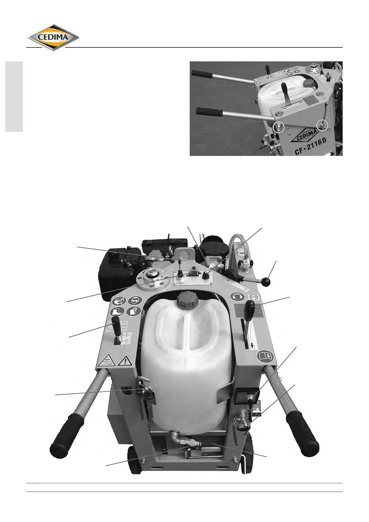
4.3 CF-2116 D control elements
Fig. 4.8
horn, lack of motor oil
switch ON/OFF water pump
lever for motor speed with
emergency-stop function
feed lever
motor control box
water connection
with shut-off valve
battery
shut-off valve,
water tank
tools
feed clutch lever
fuse box
lever for lowering/lifting of
cutting shaft