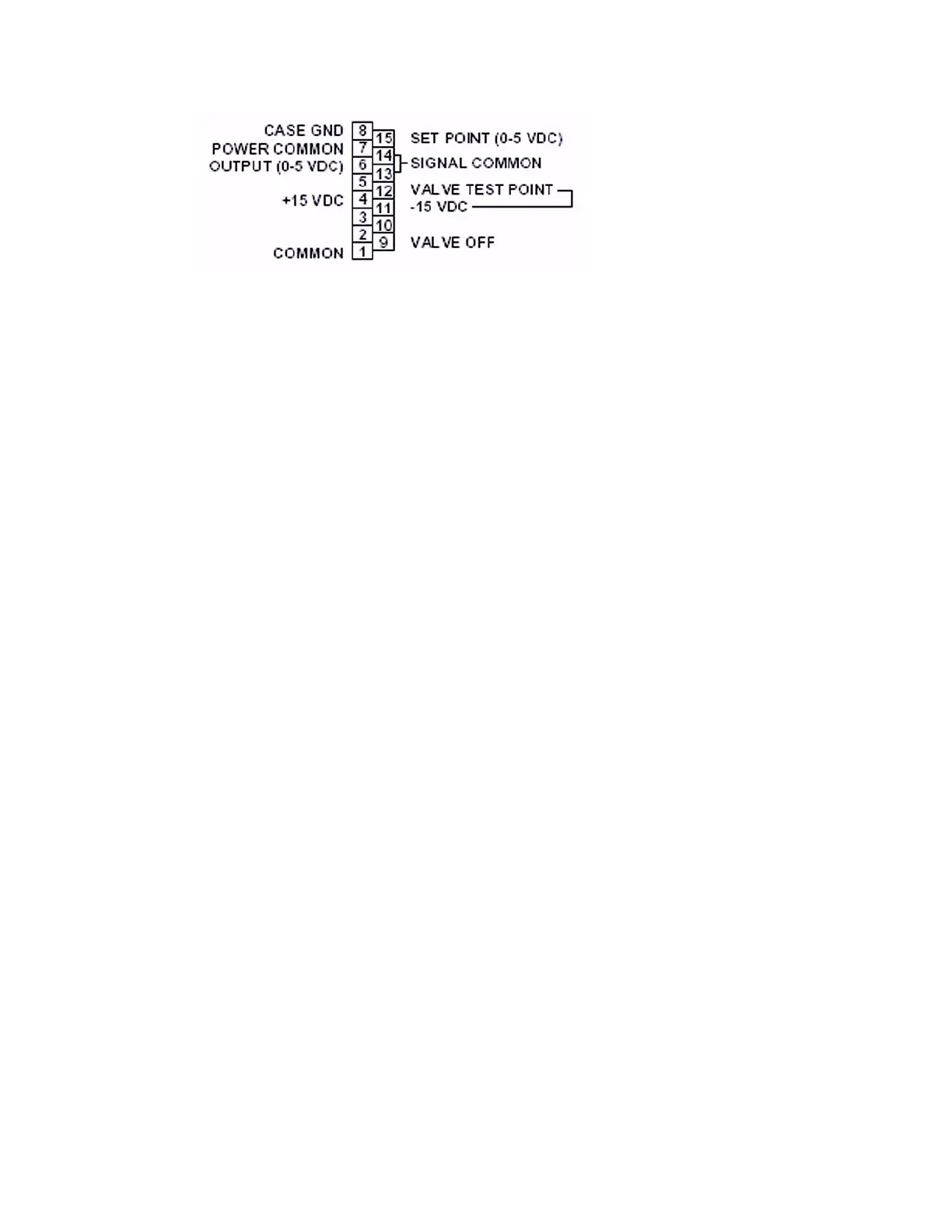
Figure 4. 9000 Series Remote “D” Connector Option Pinout (UDU15)
16.3.6 Purge
Prior to introducing process gas, insure that the MFC and gas lines have been thoroughly
purged with clean, dry N2.
16.3.7 Zero Check (For High Temp Controllers)
The electrical zero should be regularly monitored and adjusted accordingly, using the
zero adjustment.
16.3.7.1 Ensure that the flow controller has been ON for more than 60 minutes
and the flow controller is at its operational temperature.
- The High Temperature controllers have a calibration temperature
window that is ±15°C from the nominal operating temperature.
16.3.7.2 Shut OFF the inlet and outlet gas supply lines to the flow controller,
making sure that no gas is flowing through the controller.
16.3.7.3 The flow signal output should read a steady 0. If the output is not within
±0.5%(±25 mV) of 0.0 V, then remove the small inspection label on the
Remote electronics and press the Zero button.
- For best performance the Zero should be within ±0.2% (±10 mV).
See drawing 990-111-9660U for zer
o adjustment access.
Note: For r
emote r
eadouts, including analog to digital conver
ters, ensur
e that the
readouts match the 9000 Series signals. Adjust the remote readout zero and
full-scale to match the 9000 Series signals.
16.3.8 Calibration Check (For High Temp Controllers)
Calibration must be checked by flowing gas through a calibration reference and then
through the mass flow controller to verify correct readout.
Celerity recommends that all High Temperature metal seal controllers be returned
to Celerity for r
e-calibration.
22
©2005 Celerity
, Inc.
#199-001-0006 REV
.F 4/05
Artisan Technology Group - Quality Instrumentation ... Guaranteed | (888) 88-SOURCE | www.artisantg.com