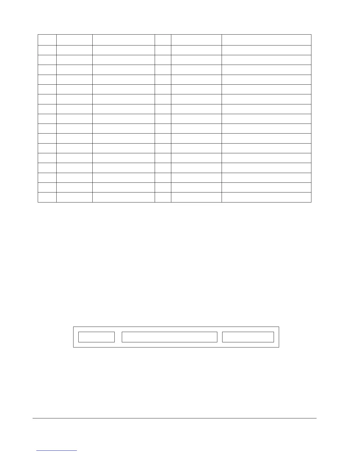
Pin Name Description Pin Name Description
9 DD4 Data 4 10 DD11 Data 11
11 DD3 Data 3 12 DD12 Data 12
13 DD2 Data 2 14 DD13 Data 13
15 DD1 Data 1 16 DD14 Data 14
17 DD0 Data 0 18 DD15 Data 15
19 GND Ground 20 (KEY) Key (pin missing)
21 DMARQ DMA Request 22 GND Ground
23 /DIOW Write Strobe 24 GND Ground
25 /DIOR Read Strobe 26 GND Ground
27 IORDY I/O Ready 28 SPSYNC:CSEL Spindle Sync or Cable Select
29 /DMACK DMA Acknowledge 30 GND Ground
31 INTRQ Interrupt Request 32 /IOCS16 I/O Chip Select 16
33 DA1 Address 1 34 PDIAG Passed Diagnostics
35 DA0 Address 0 36 DA2 Address 2
37 /IDE_CS0 (1F0-1F7) 38 /IDE_CS1 (3F6–3F7)
39 /ACTIVE Led driver 40 GND Ground
64-Bit PCI Connectors
The Peripheral Component Interconnect (PCI) 64-bit connector is a 23-pin 3.3 V-style card edge
connector. 3.3V indicates PCI signaling levels. The connector is illustrated in Figure 33, with pin
assignments listed in Table 11.
A1
B11
A14 A62 A63
B94B1 B14 B62 B63
A94
Figure 33. 64-Bit PCI Connector
Appendix - 12


 To Next Page