www.cellarcool.com | Page 23
Magnum Series
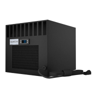
1. Unscrew and remove the top, rear and side access panels.
2. Remove the knockout(s) that you will be using to route
the items on page 24 into the unit (line set, power wires,
display cable, and bottle probe cable). See knockout
options on page 7. Also remove insulation from behind the
knockout holes.
3. Route the liquid and suction lines through the knockout in
the housing.
4. Connect line set piping according to instructions.
5. Install condensing unit before proceeding.
6. Route the power wires into the unit.
7. Connect the line voltage wire to the lever connector
labeled “L.”
8. Connect the neutral wire to the lever connector labeled “N.”
9. Connect the ground wire to the green bare-end wire
labeled “GROUND.”
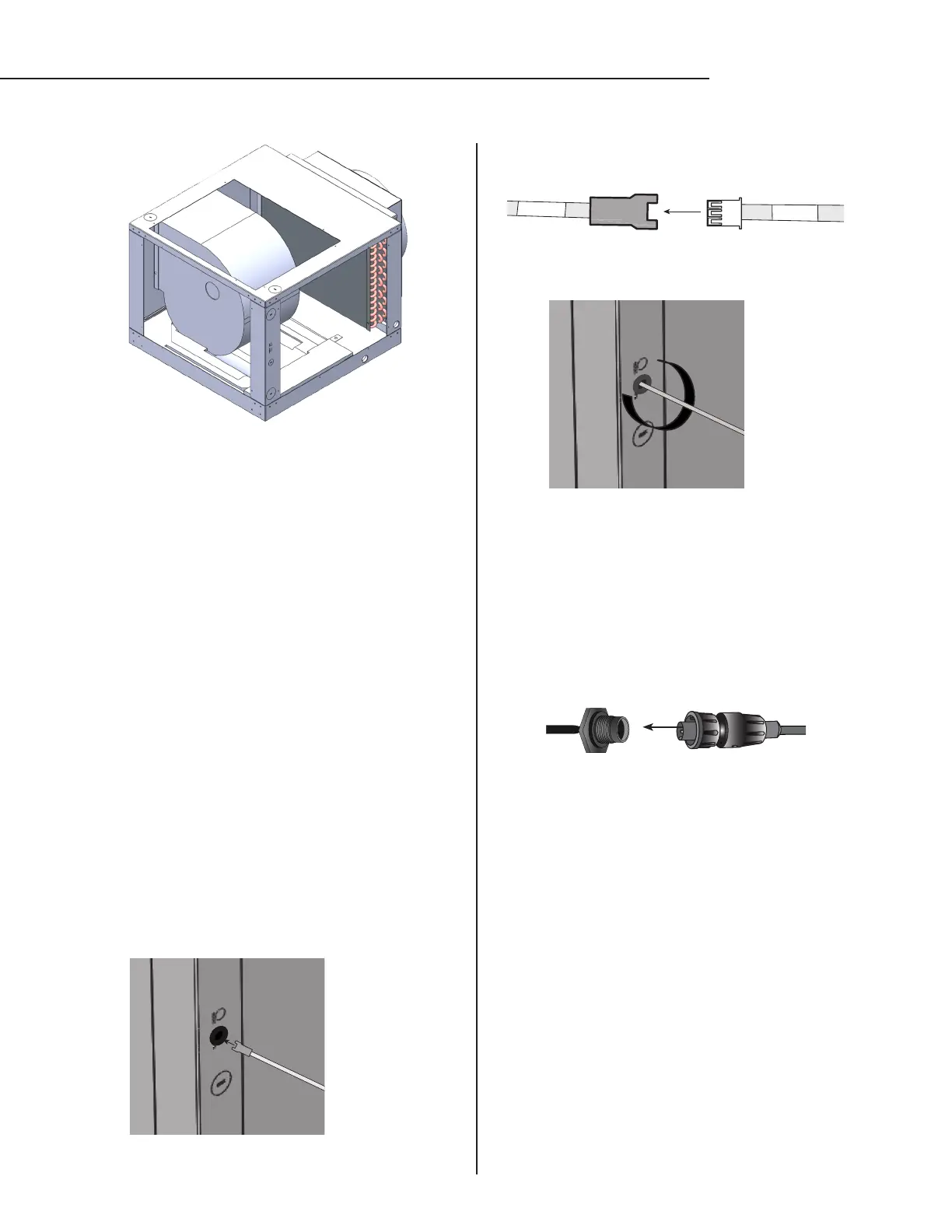
10.. Install one of the 13/32” grommets in the hole labeled
“DISPLAY.”
11. Route the display cable through the knockout and into the
unit as shown in Figure 1.
INSTALLING THE EVAPORATOR UNIT*
12. Connect the end of the display cable labeled “UNIT” to
the wire labeled “UNIT” coming from the controller box.
13. Install the supplied piece of cork tape around the display
cable as shown in Figure 2.
14. Route the display cable to the desired location.
15. Remove the nut from the circular connector wire which is
located in the corner behind the bottle probe knockout.
16. Insert the circular connector into the hole labeled
“BOTTLE PROBE” and secure using the nut removed in
previous step.
17. Connect 50-foot bottle probe to circular connector on
exterior of unit.
18. Insulate the suction line using Armaex or similar
insulation.
19. Set torque setting on drill to 8 lbs and reinstall the top,
rear, and side panel using the screws removed.
25. Using Nashua foil tape or equivalent, cover all seams.
NOTE: Do not tape over the drip tray access port.
*Ensure that the left side of the evaporator unit (where the
electrical box is located) remains accessible after installation.
UNIT
UNIT
FIG. 1
FIG. 2
 Loading...