Page 28
TWIN MG 092223
3
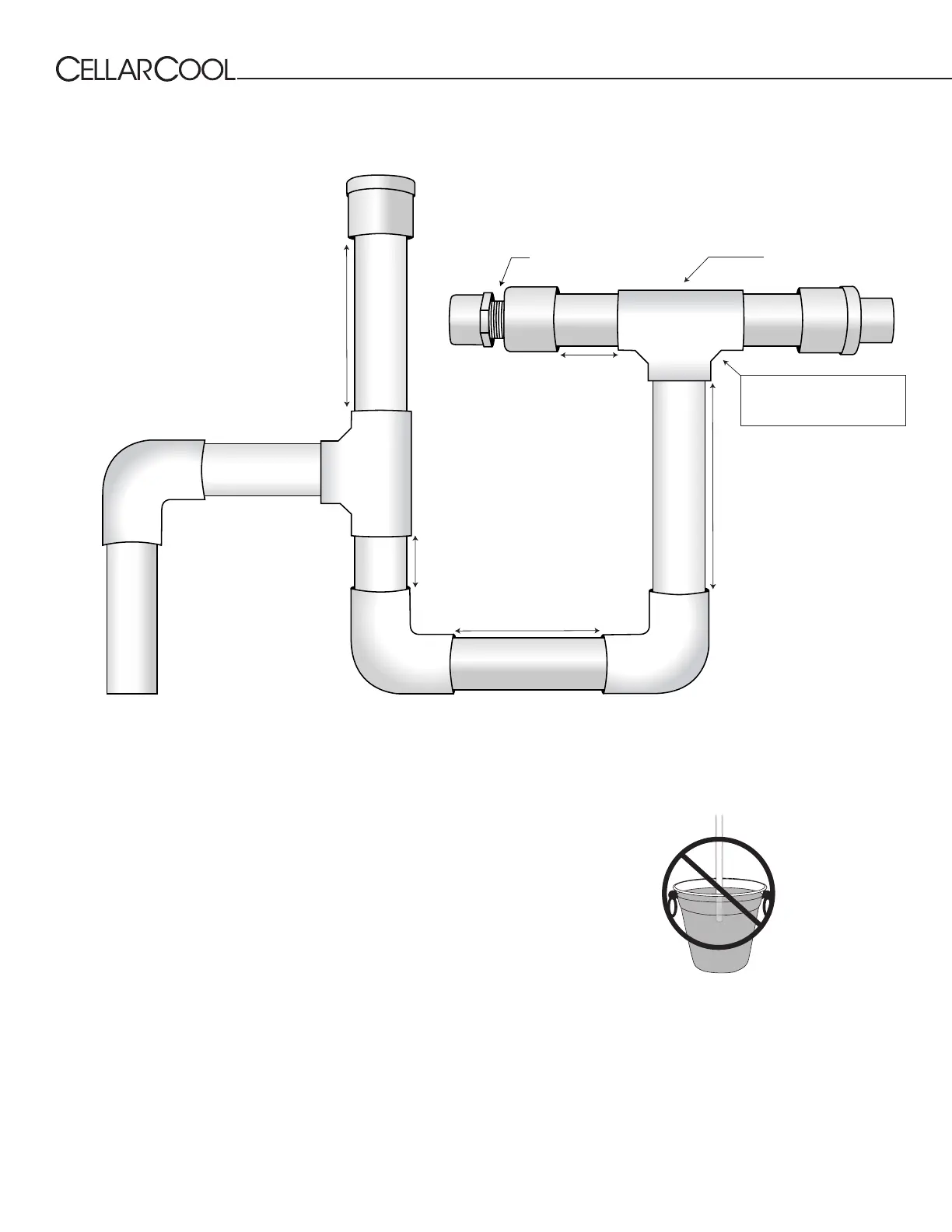
/4” CPVC tee
3
3
/4”
3
/4” CPVC 90-degree elbow
2
3
/8”
3
/4” CPVC cap
3
/4” CPVC tee
3”
3
/4” CPVC cap with
1
/4”
drilled hole (NOT SHOWN)
3
/4” CPVC 90-degree elbow
3
/4” CPVC 90-degree elbow
1
1
/16”
2
5
/8”
NOT TO SCALE
THIS TEE MUST BE
ROTATED SLIGHTLY TO
ALLOW ACCESS TO CAP
Below is a detailed diagram of how the P-trap should be constructed.
WRONG: Drain line is under water.
PTRAP CONFIGURATION
Connecting the Drain Line
Apply CPVC primer and glue to the female tting coming from the
unit and the CPVC tube which will be connected to it.
Insert the a piece of CPVC tubing into the female tting.
Route additional CPVC tubing to an appropriate discharge location.
(Tubing is not provided.)
Every six weeks, remove the ¾” CPVC cap and run a drain line brush
through the T-junction until all sludge and slime is removed.
To prevent mold from growing and to
ensure proper drainage, allow the drain
line to hang above the waterline.
NOTE: Use a soft tube-cleaning brush to clean out the drain
line. Failure to use a soft brush could damage the
drip tray of the unit and void the warranty.
TO
UNIT