Condensing Pool Heater 13 17/11/06
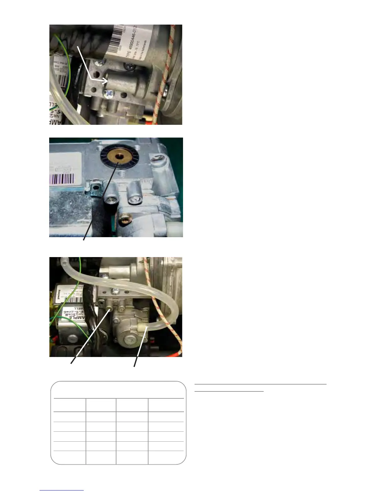
Inlet pressure
tapping
Offset
connection
Rating Table (1040 Btu/ft³) (38.8 MJ/m³)
kW gross Btu/h sec/ft³ m³/2 mins
7.5 25590 145 0.023
12.5 42650 87 0.039
20 68240 55 0.062
34.6 108055 31.5 0.107
52 177420 21 0.161
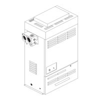
Condensate Connection
The direction of the plastic condensate drain pipe
connection can be altered from the factory position on
the left, to the right.
Remove the blanking plate from the left hand
side (See Fig. 3.1)
Loosen the two screws holding the Trap
bracket and swivel the trap through 90 degrees.
Secure the bracket and fit the supplied 40 mm
pipe.
Example installations are shown in Fig 7.1.
Fit blanking plate to the right hand side.
(See Fig 7.1)
Where possible an internal termination of the conden-
sate discharge pipework should be used.
. If this is not psossible external pipes should be kept
as short as possible and insulated.
Where fitted in pipework that includes another trap an
Air Break should be fitted between the Heater and
that trap.
Avoid connecting to a kitchen sink trap as the solids
and fats in the drain will cause a blockage.
It is permissible to connect to an external gully or rain
water hopper provided they connect to a combined
system.
The condensate should not be run into a ‘grey water’
system.
If the condensate pipe is connected to a stack it
should join not less than 450 mm above the foot of
the stack. In addition it should be positioned so there
no chance of cross-flow to another connection.
Installation pipework must be in Osma 40 mm plastic
pipe to a suitable drain location with a gradient of 2.5°
(45mm/ metre run) minimum. If connected to another
drainage trap, an air break is required between the
Heater drain and that trap. (See Fig.7.0 & 7.1).
External runs, should, if possible, be insulated to
defer problems from freezing.
Check during commissioning to prove there is a
leakfree working connection from the Heater to the
drain. The simplest way to do this is to carefully pour
some water into the boiler flue and check it emerges
at the drain.
The “Guide to the Condensing Boiler Assesment
Procedure for Dwellings” can be refered to, see
http://www.planningportal.gov.uk/england/profession-
als/en/1115314255842.html
Fig. 6.0
Fig. 6.2
Throttle
Adjustment
Fig. 6.1
Orifice in position