3-49
0
1
2
3
4
5
6
7
8
9
10
11
12
13
14
15
16
17
18
19
20
21
E
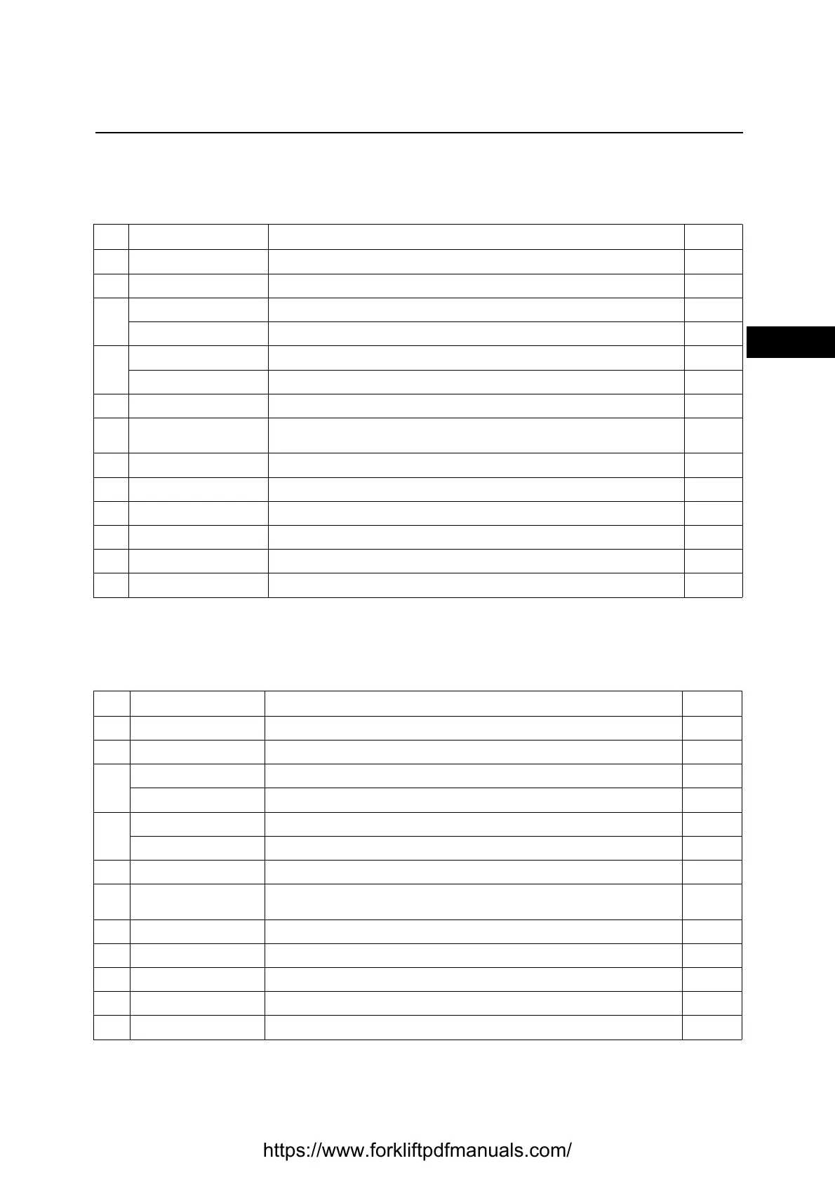
MAT. HANDLING
Mechanical lever control valve
Displays the hydraulic system settings for the mechanical version
MAT. HANDLING
Electro-proportional distributor
Displays the hydraulic system settings for the electro-proportional version
Ref. Parameter Description Notes
1LIFE PUMP Pump working hour counter from the first start Hours
2LIFE KEY Key working hour counter from the first start Hours
3
SPEED SET Theoretical speed requested to the pump motor Hz
MOT SPEED Pump motor encoder frequency Hz
4
MOTOR TEMP Pump motor temperature °C
CONTR TEMP Temperature of the pump logic unit °C
5MOT SLIP Speed difference between the rotating field and the driving shaft Hz
6 MOTOR VOLTAGE
Voltage applied to the motor by the logic unit
Expressed as a percentage of the maximum applicable
%
7LIFT Lifting lever microswitch ON-OFF
8TILT Tilting lever microswitch ON-OFF
9 SIDESHIFT Sideshift lever microswitch ON-OFF
10 IV WAY 4th way microswitch ON-OFF
11 V WAY 5th way microswitch ON-OFF
12 LIFT POT Lifting potentiometer signal voltage V
Ref. Parameter Description Notes
1 LIFE PUMP Pump working hour counter from the first start Hours
2LIFE KEY Key working hour counter from the first start Hours
3
SPEED SET Theoretical speed requested to the pump motor Hz
MOT SPEED Pump motor encoder frequency Hz
4
MOTOR TEMP Pump motor temperature °C
CONTR TEMP Temperature of the pump logic unit °C
5MOT SLIP Speed difference between the rotating field and the driving shaft Hz
6 MOTOR VOLTAGE
Voltage applied to the motor by the logic unit
Expressed as a percentage of the maximum applicable
%
7LIFT Lifting potentiometer signal voltage V
8TILT Tilting potentiometer signal voltage V
9SIDESHIFT Sideshift potentiometer signal voltage V
10 IV WAY 4th way potentiometer signal voltage V
11 V WAY 5th way potentiometer signal voltage V
https://www.forkliftpdfmanuals.com/