CESSNA AIRCRAFT COMPANY FOR TRAINING USE ONLY
MODEL 152 9-26
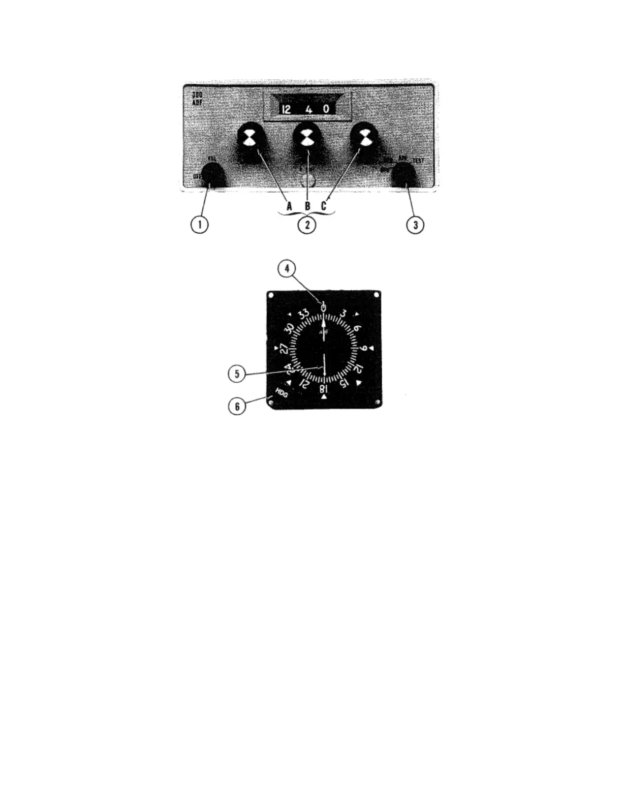
Figure 1. Cessna 300 ADF Operating Controls and Indicators
1. OFF/VOL CONTROL – Controls primary power and audio output level. Clockwise rotation from OFF
position applies primary power to receiver; further clockwise rotation increases audio level.
2. FREQUENCY SELECTORS – Knob (A) selects 10-kHz increments of receiver frequency, knob (B) selects
10-kHz increments, and knob (C) selects 1-kHz increments.
3. FUNCTION SWITCH:
BFO: Selects operation as communication receiver using only sense antenna and activates
1000-Hz tone beat frequency oscillator to permit coded identifier of stations
transmitting keyed CW signals (Morse Code) to be heard.
REC: Selects operation as standard communication receiver using only sense antenna.
ADF: Set operates as automatic direction finder using loop and sense antenna.
TEST: Momentary-on position used during ADF operation to test bearing reliability. When
held in TEST position, slews indicator pointer clockwise; when released, if bearing is
reliable, pointer returns to original bearing position.
4. INDEX (ROTATABLE CARD) – Indicates relative, magnetic, or true heading of aircraft, as selected by
HDG control.
5. POINTER – Indicates station bearing in degrees of azimuth, relative to the nose of the aircraft. When
heading control is adjusted, indicates relative, magnetic, or true bearing of radio signal.
6. HEADING CONTROL (HDG) – Rotates card to set in relative, magnetic, or true bearing information.