13
INSTALLING THE PROTECTOR SYSTEM
TM
(OPTIONAL IR BEAMS)
21
NOTE: This accessory must be used for all installations where
t
he closing force as measured on the bottom of the door is
over 400 N (40 kgf).
SPECIAL NOTE: Chamberlain strongly recommends that The
Protector System
T
M
(IR BEAMS) be installed on all garage
door openers.
The Protector System
TM
(IR BEAMS): By installing The Protector
System
TM
(IR BEAMS), an open door is prevented from closing if a
p
erson or object is located in the beam area. If the door is already
closing, it will return to the open position. A closed door is not
prevented from opening.
If The Protector System
TM
(IR BEAMS) is installed and needs to be
removed, the opener will need to be reprogrammed (refer to
paragraph 4 of the troubleshooting section).
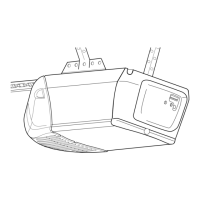
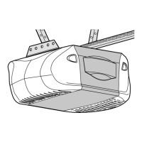
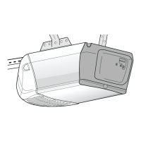
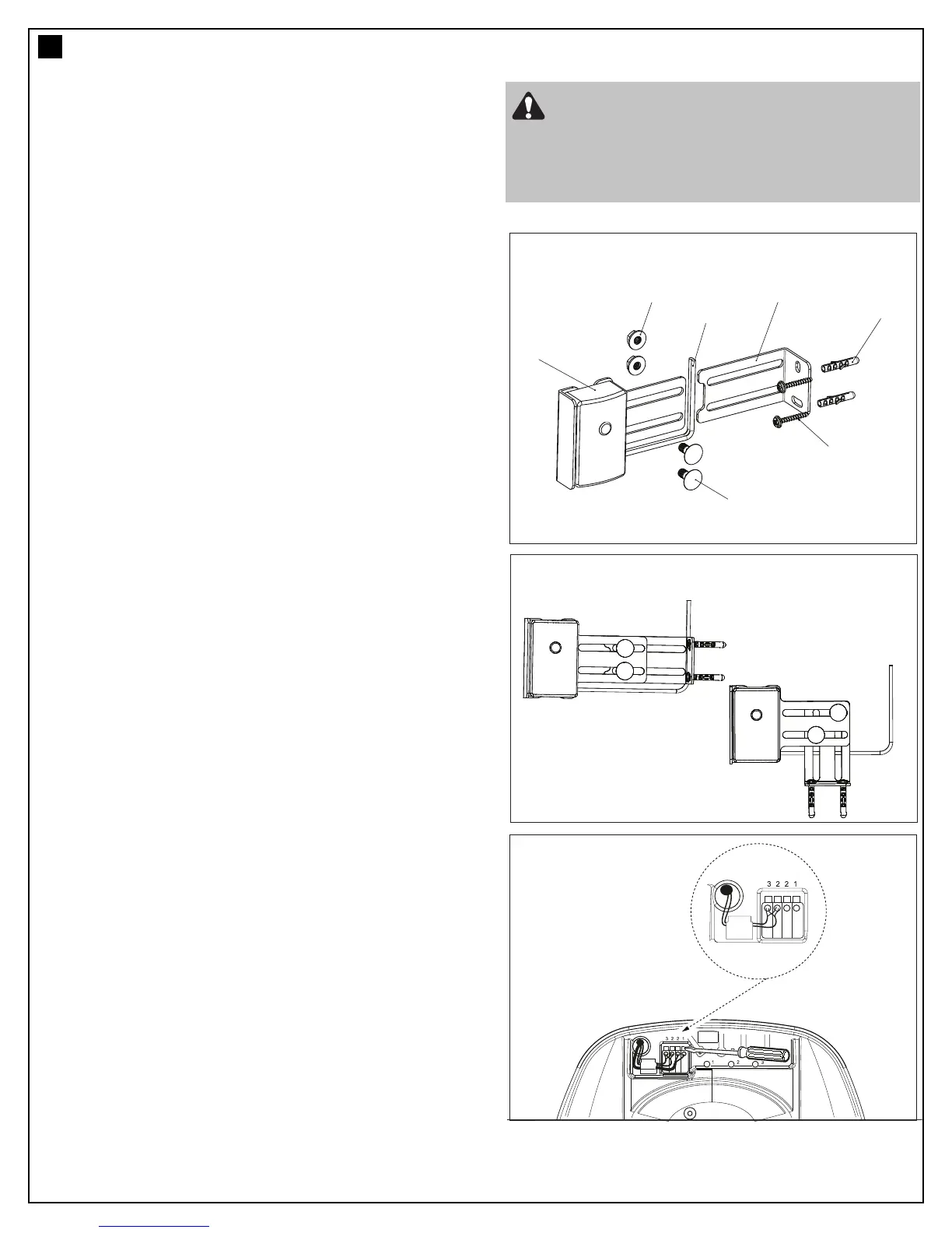
Assembly Process:
The Protector System
TM
(IR BEAMS) is supplied preassembled, complete
with two sensors, wiring and wall brackets. (figure 1 & figure 2)
Install the mounting brackets and sensors to either side of the
inside of the garage door, and at a height of no greater than 100
mm off the garage floor.
The brackets are designed to be used for Wall (view 1) or Floor
(view 2) fixing, with a variety of hole combinations to achieve the
desired results.
Drill the required holes and install the brackets with wall plugs and
screws provided. Ensure they do not obstruct the door movement.
Wiring Process:
Align the sensors to face each other and tighten if necessary. The
wiring should exit from the bottom of the housing to maintain the
correct IP rating and continued operation.
One sensor is a Sending Eye , the other is a Receiving Eye. Try to
avoid positioning these in direct sunlight as this may interfere with
the operation of the beams.
Run both sets of wire back to the power head CONTROL PANEL
(refer page 5). Ensure the wire is well supported and does not
interfere or get damaged by movement of the door panels or spring
hardware.
Disconnect Power from the Unit:
At the power head end, cut the wires to the correct length and strip
each back around 10 mm.
Twist both White wires together and install into “quick release”
terminal 2 (white) (fig 3)
Twist both Black/White wires together and install into “quick
release” Terminal 3 (Grey) (fig 3)
(The sensors are a 2 wired system connected in a parallel
configuration).
Reconnect Power to the Unit:
When aligned correctly the Red LED on each sensor will remain
“ON” constantly.
If incorrectly aligned both LED will “flash”.
Correct the alignment if necessary.
The opener is now ready to be checked for correct IR BEAM
operation.
Note: Refer to installation and test instructions as included in
The Protector System
TM
(IR Beam) kit.
LLAWCISTALP
G
ULP
L
LAW
WERCS
L
LAW
TEKCARB
EGNALFM6
TUN
HCAOCM6
WERCS
774AML
IR BEAM
2 CORE
ELBACREIW
3 = Black/White x 2
2 = White x 2
figure 1
figure 2
figure 3
T
o prevent entrapment, install The Protector
System™ (IR BEAMS) no higher than 100 mm
above the floor.
Disconnect power to the garage door opener
b
efore installing The Protector System™ (IR
BEAMS).
view 1
view 2
 Loading...