36
STEP 6
SOLAR PANEL(S)
NOT PROVIDED. SEE ACCESSORIES.
Solar Application requirements:
• A minimum of one 10W solar panel (Model SOLPNL10W12V).
• A maximum of three 10W solar panels in parallel (Model SOLPNL10W12V).
• Battery Harness (Model K94-37236).
• One 7AH battery or one 33AH battery
• A heater cannot be used with a solar application.
Disconnect the expansion board if it is not in use to improve performance. We recommend LiftMaster low power draw accessories to minimize power
draw, refer to accessory page. Use the tables below to see performance trade-offs. NOTE: Input solar power is 12 Vdc at 30 watts maximum.
The solar panel(s) must be located in an open area clear of obstructions and shading for the entire day. The gate operator is not supported in northern
climates where temperatures reach below -4˚F. This is due to cold weather and a reduced number of hours of sunlight during the winter months. Cycle
rate may vary from solar chart for areas that reach below 32˚F. Solar panels should be cleaned on a regular basis for best performance to ensure
proper operation.
APPENDIX
SOLAR USAGE GUIDE
The RSL12VDC has best in class solar performance due to highly efficient electronics that draw very little power while the gate is not in use (standby).
All numbers are estimates. Actual results may vary.
Typical System Standby Battery
Current Consumption (mA)
System Configuration
4.2 mA Main control board draw with no remote controls programmed
+1.5 mA Low band radio receiver active (one or more wireless transmitters learned)
+3.9 mA High band radio active (MyQ device programmed)
+18.5 mA Expansion board (not provided)
+6.6 mA Per loop detector (up to 3 loop detectors can be plugged into the expansion board)
This low current draw drastically increases the number of days the operator can remain in standby. To determine your system’s performance,
reference the above table and determine how many milliamps (mA) your system will draw from the batteries.
EXAMPLE 1: A system with only a main control board and one or more hand held remote controls programmed will draw 5.7 mA from the batteries
while the system is in standby (4.2 mA + 1.5 mA = 5.7 mA).
EXAMPLE 2: A system with only a main control board, one or more hand held remote controls programmed, and 20 mA of external accessories
connected to the main control board's accessory power output will draw 25.7 mA from the batteries while the system is in standby
(4.2 mA + 1.5 mA + 20 mA = 25.7 mA).
EXAMPLE 3: A system with a main control board, expansion board, two loop detectors, and one or more hand held remote controls programmed will
draw 18 mA from the batteries while the system is in standby (4.2 mA + 18.5 mA + 6.6 mA*2 +1.5 = 37.4 mA).
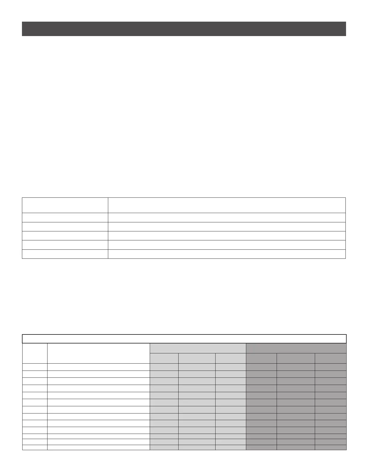
Operator performance with no sun or loss of AC power
BATTERY
CURRENT
DRAW (mA)
SYSTEM CONFIGURATION DAYS OF STANDBY GATE CYCLES ON BATTERY
7AH battery Two 7AH Batteries 33AH battery 7AH battery Two 7AH Batteries 33AH battery
4.2 main control board only 85 171 180 114 281 710
5.7 remote controls programmed 63 126 180 114 281 710
9.6 remote controls and MyQ programmed 37 75 163 114 281 710
24.2 remote controls and expansion board 15 30 64 114 281 709
30.8 remote controls, expansion board, and one loop detector 12 23 51 114 281 709
44 remote controls, expansion board, and three loop detectors 8 16 35 114 280 709
50 7 14 31 114 280 709
60 6 12 26 114 280 709
80 4 9 19 114 280 708
100 4 7 16 114 279 708
200 2 4 8 113 278 705
300 1 2 5 112 276 703
500 1 1 3 110 273 698