Rev C Doc 6001242 (01-20273) 7 of 53
C. POWER WIRING
1. Provide a separate conduit stub for the AC power.
2. Each gate operator requires a 115 VAC 20 AMP single phase circuit. NOTE: Master and
Slave units each require separate circuits to prevent false overcurrent faults.
3. Be sure to pull a ground wire in the conduit for the connection to the gate operator. Do not rely
on metallic conduit for earth ground.
D. LOOP DETECTORS
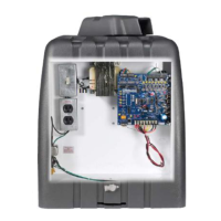
1. The gate operator has a shelf that can support non-LiftMaster loop detector electronics.
Power for the loop detector can come from the auxiliary 115 VAC plugs in the gate operator or
from the 24 VAC provided by the gate operator control board.
2. Conduit provisions should be made for the “loop” wire entrance to the loop detector.
3. The shelf space provided is approximately 4” x 10” x 5” high. Shelf space on systems without
the Power Fail Operation Option is about 10" x 10" x 5".
NOTE: Optional LiftMaster-supplied loop detector add-on boards are available, both pre-installed
and for installation in the field. See Part 4, SW 2000-B1 Options.
E. OTHER CONNECTIONS
Provisions should be made for conduit entrance into the gate operator for Master/Slave wiring and
external activating devices such as key switches, telephone entry systems, etc.
INSTALLATION NOTES