4.
INSTALLATION
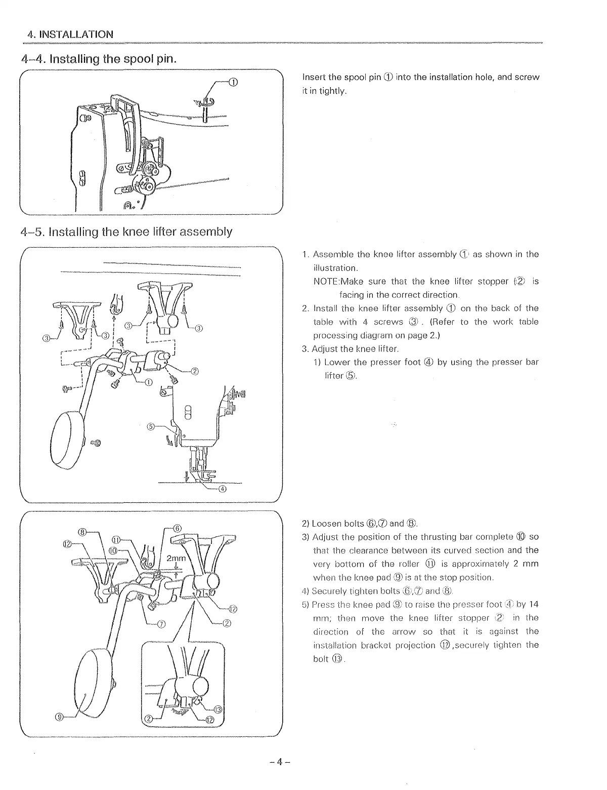
4~4.
Installing the spool pin.
4-5.
Installing the knee lifter assembly
-4-
Insert
the
spool pin
CD
into the installation hole, and
screw
it
in
tightly.
1.
Assemble
the
knee lifter assembly
as shown
in
the
illustration.
NOTE:Make sure that the knee lifter stopper
fZ:;
is
facing
in
the correct direction.
2.
Install
the
knee lifter assembly
CD
on the back of
the
table
with
4
screws
(Refer
to
the
work
table
processing diagram on page 2.)
3.
Adjust
the knee lifter.
1)
Lower
the
presser
foot
@
by
using the presser bar
lifter®.
2)
Loosen bolts
@.(1)
and
(til
3)
Adjust
the
position
of
the thrusting bar complete ® so
that
the
clearance
between
its curved section and
the
very
bottom
of
the
roller @ is approximately 2
mm
when
the
knee pad
(9)
is
at the stop position.
4)
Securely tighten bolts and
G)
Press the knee pad
to
mise the presser
foot
!f
by 14
mm;
then
move
the knee lifter stopper
:z
in
the
direction of the
arrow
so that it
is
against
the
installation bracket projection
@,securely
tighten
the
bolt@.
From the library of: Superior Sewing Machine & Supply LLC
 Loading...