Page 3
Page 2
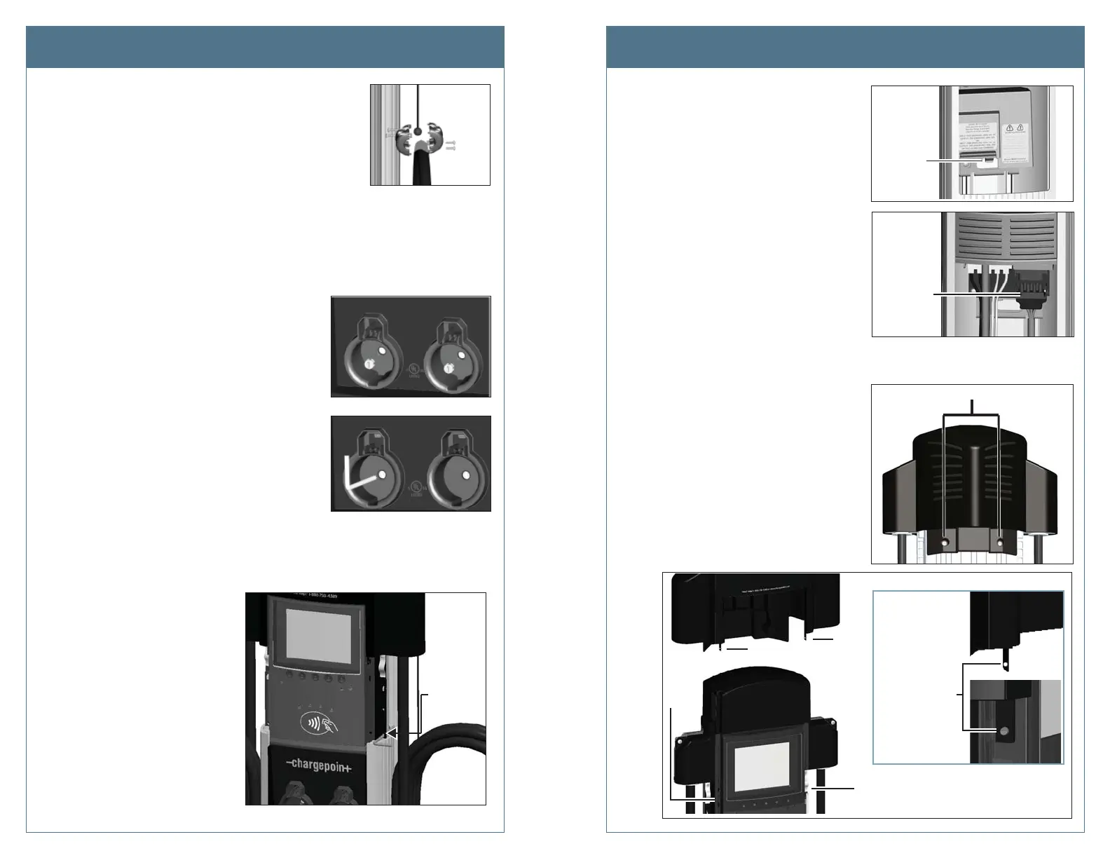
Step 7: Push the black tab on the terminal block
to release the terminal block cover, then
slide the cover up until it locks into the
raised position.
Step 8: Disconnect the blue connector by
pressing the side tabs while rocking
the connector side to side and pulling
downward.
Step 9: Remove the L-wrench you inserted
in Step 6 and lift the existing head
assembly upwards to remove.
Step 10: Place the removed head assembly on
the shipping box to prevent damage
when completing the next step.
Step 11: Using a Phillips screwdriver, remove the
two screws from the back of the top
cap.
Step 12: While using your fi ngers to release
the top cap’s two retention tabs from
their corresponding nodules (as shown
below), pull the top cap upwards to
remove.
Step 1: Remove the cable clamp(s) by loosening its four screws
using a Phillips screwdriver.
Step 2: With the station powered on, scan your ChargePoint card, then remove the charging
plug(s) from the holster(s).
IMPORTANT! You must scan an activated ChargePoint card to unlock the holster(s)
and remove the charging plug(s).
Step 3: Disconnect the station’s power at the electrical panel.
Step 4: Use pliers to remove the rubber plug(s),
located inside the holster(s).
Step 5: Open the shipping box for the new head
assembly and remove the T25 L-wrench from
the side of the new head assembly (illustrated
on the previous page). Use this L-wrench to
loosen the security set screw(s) located
inside the holster(s).
TIP! After removing the T25 L-wrench from the
new head assembly, close the shipping box—the
top of the box is a place you can support the
removed head assembly, as
described in Step 9.
Step 6: Raise the head assembly high
enough to access the terminal
block. To hold the head assembly
in the raised position, insert the
L-wrench into the thru-hole on
the side of the head assembly.
This hole is located on the right
side of the head assembly and
is marked with the screwdriver
symbol.
Pull the
blue
connector
down to
release
Push tab
and lift
cover
Remove these 2 screws
Lift the tab on
each side of the
top cap to release
it from its
corresponding
nodule on the
head asembly
Tab
Tab
Nodule
Nodule
Remove the Existing Head Assembly Remove the Existing Head Assembly
L-wrench
Insert the
L-wrench
into the
thru-hole