CERT-iS3 MNL, CDM-10000105, 106, 107, 108, 109, 110,
113, 119, 167, 188, 191, 192
THIS DRAWING OWNED BY CHENTRONICS. IT IS
CONDITIONALLY LOANED AND IS TO BE RETURNED UPON
REQUEST. THE BORROWER BY RECEIVING IT HAS AGREED
NOT TO REPRODUCE NOR COPY IT IN WHOLE OR IN PART NOR
TO FURNISH INFORMATION FROM IT TO OTHERS NOR TO
MAKE ANY USE OF IT THAT IS OR MAY BE INJURIOUS TO
CHENTRONICS. FOR MORE INFORMATION, PLEASE CONTACT
CHENTRONICS AT +1.607.334.5531.
Technical Specification NOTES
Note 1 Purge air pressure is the minimum differential pressure required between the purge air
supply pressure at “Y” (scanner connection) and the back pressure.
Note 2 24 VDC Power supply to iScan®3 Flame Scanner must not include any inductive load.
Note 3 To achieve higher relay contact voltages, use iScan®3 Flame Scanner relay contacts to
energize the coil of an interstitial relay.
Note 4 Output for monitoring only. Not to be used to prove flame.
Note 5 4-20 mA outputs are calibrated at the factory to a known load. Monitoring hardware will
have an impact on the current output. For accurate readings, 4-20 mA output(s) should be
calibrated using a milli-ammeter between the scanner’s 4-20 mA output and the monitoring
hardware. For details on executing the calibration procedure, refer to the 4-20 mA settings
section of MNL-iScan Software.
Note 6 SUGGESTED SIL3 PROOF TESTS:
An annual proof test is a good practice to meet the requirements of IEC61508. According
to section 7.4.3.2.2 f of IEC61508, proof tests shall be undertaken to reveal dangerous faults
that may be undetected by diagnostics.
Flame OFF: Shut down the burner and ensure the flame off condition is detected and
signaled by the flame detector as a flame off condition.
False Flame: Verify that before start-up (no flame present), there is no indication of a flame
on condition (false flame signal) on the flame scanner (this is typically integrated within the
BMS as a pre-start permissive to prevent start-up if a false flame condition is detected. The
BMS test should not be considered a replacement for recommended testing of the scanner
adjustments, which must be verified each time the scanner is commissioned, adjusted,
settings are changed, or re-commissioning takes place. In these cases, only qualified
personnel who have been trained and are experienced should make such adjustments.
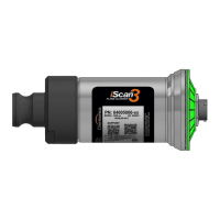
4.0 Wiring Instructions
All wiring shall be done per all applicable local and national codes, standards, and ordinances. The scanner
has a quick connect cable. This cable does not require a flexible conduit if the local authority permits.
Connections for power, Earth Ground, and Flame Relay (N.O. and Common) are needed for all
applications. Use of the 4-20 mA outputs and Communication connections are “as required” for each
application.