RELATED DOCUMENT – MUST COMPLY WITH SCHEDULE DOCUMENT(S):
CERT-iS3 MNL, CDM-10000105, 106, 107, 108, 109, 110,
113, 119, 167, 188, 191, 192
FOR A LIST OF RELEVANT PATENTS
AND TRADEMARKS PLEASE SEE
CHENTRONICS.COM/LEGAL-NOTICES
THIS DRAWING OWNED BY CHENTRONICS. IT IS
CONDITIONALLY LOANED AND IS TO BE RETURNED UPON
REQUEST. THE BORROWER BY RECEIVING IT HAS AGREED
NOT TO REPRODUCE NOR COPY IT IN WHOLE OR IN PART NOR
TO FURNISH INFORMATION FROM IT TO OTHERS NOR TO
MAKE ANY USE OF IT THAT IS OR MAY BE INJURIOUS TO
CHENTRONICS. FOR MORE INFORMATION, PLEASE CONTACT
CHENTRONICS AT +1.607.334.5531.
TOLERANCE NOTES
FABRICATED TOLERANCES
≥ 2 ft (610 mm) ± 0.250 in (6.4 mm)
< 2ft (610 mm) ± 0.125 in (3.2 mm)
MACHINED TOLERANCES
± 0.050 DECIMAL DIM (1 PLACE)
± 0.010 DECIMAL DIM (2 PLACES)
± 0.005 DECIMAL DIM (3 PLACES)
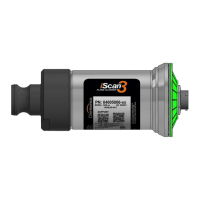
4.2 Cable Connection
Figure 5: PN: 04005000-SB/MB with locking nut and I/o cable
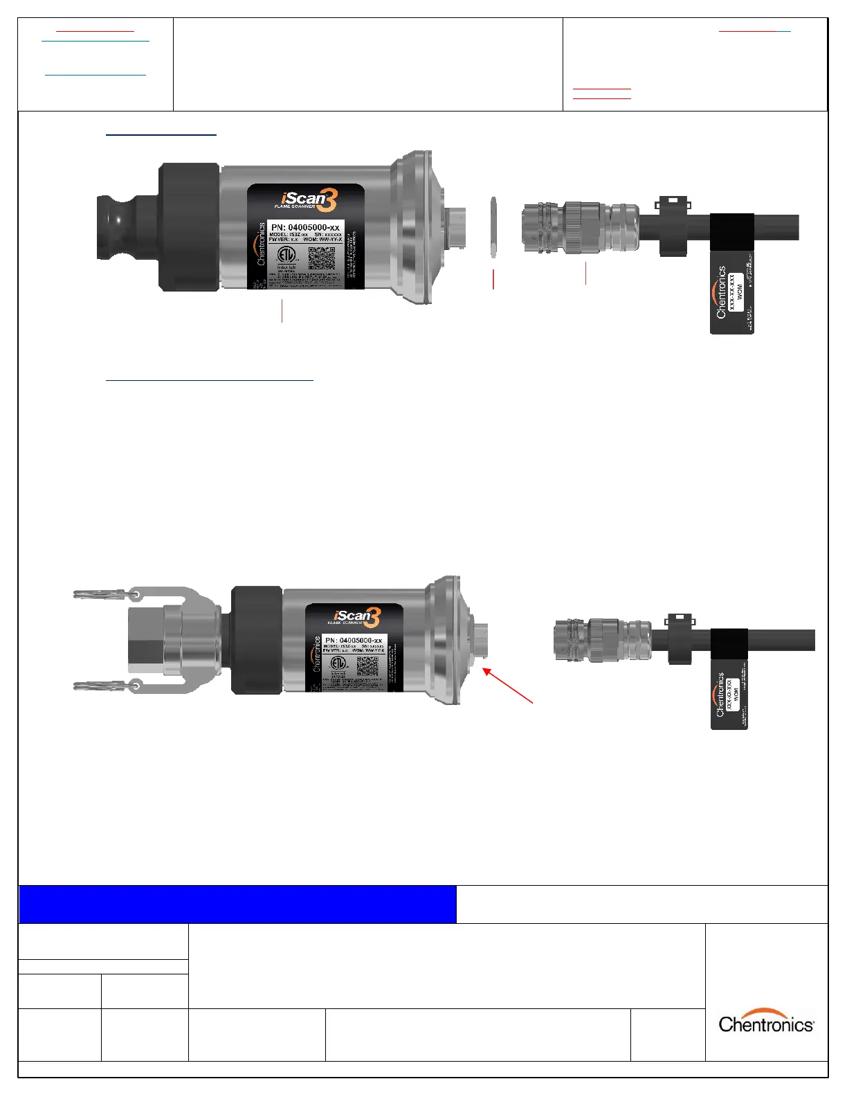
4.3 Power/Control Cable Installation
The iScan®3 Flame Scanner system utilizes a quick disconnect connector to connect the power/control
cable to the electronics.
To connect the power cable to the electronics, turn the locking nut clockwise by hand until it is seated
against the electronics. This will ensure the locking nut is not too far out and allow the connector to
properly seat. Then, align the connector on the cable with the connector on the electronics, insert the
connector, and turn the outer barrel clockwise until the banjo fittings on the connector are seated and
latched.
Figure 6: Clear the locking nut, then align and insert the cable connector.
LOCKING NUT
(TURN CLOCKWISE
UNTIL SEATED)