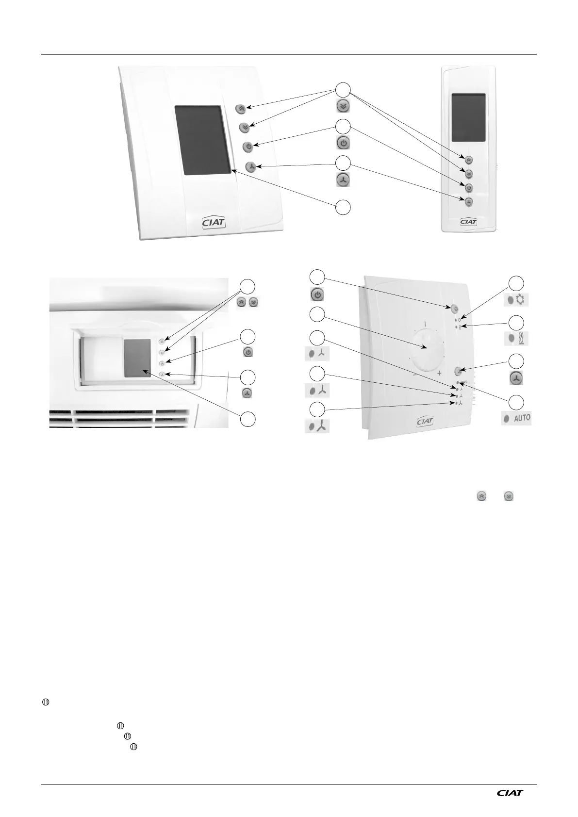
1 - USER TERMINAL AND RADIO-FREQUENCY REMOTE CONTROL
Display
terminal
Radio-frequency
Remote control
1
2
3
4
Dial terminal
Flush-mounted terminal
10
11
3
5
8
9
7
6
4
3
4
2
1
Display:
- This continuously displays the temperature detected by the sensor, the current operating mode, the chosen ventilation
speed, and any alarm present.
- If you press the buttons
,
scale appears, and you can modify the desired temperature by pressin
or .
The
temperature measured by the sensor is displayed again 8 seconds after the last time button
.
was pressed.
- It also displays error messages, reports windows opened or emergency switch-off activation, thereby enabling an initial
diagnostic.
T
emperature adjustment buttons
:
- These enable you to adjust the temperature setpoint and also access the set-up and diagnostic values
.
Standby button
:
- This enables you to change the operating mode (comfort, standby, economy, frost protection according to the chosen
set-up).
Ventilation button
:
- This enables you to select the ventilation speed (Auto, I, II, III) if the controller is in comfort, or switch to comfort mode if
the controller is in standby (see close-up of display below)
Temperature adjustment dial
Cold indicator. If lit, this indicates refrigeration
Heat indicator. If lit, this indicates heating
Automatic ventilation indicator
Low speed ventilation indicator
Medium speed ventilation indicator
High speed ventilation indicator
Note on Ventilation speed indicator operation:
*
If only
-
or lit =
Current manual speed selected.
* If
+ (
or
or ) =
Current speed given by controller AUTOMATIC position
.
Si un des voyants
à est éclairé, alors le régulateur est en régime confort
Note:
The wall terminals are interchangeabl
e.
EN7515935-00 EN - 2