MIG (GMAW) WELDING 5-10 Manual 0-5492
5.10 Setup for MIG (GMAW) Welding with Gasless MIG Wire (Flux Cored)
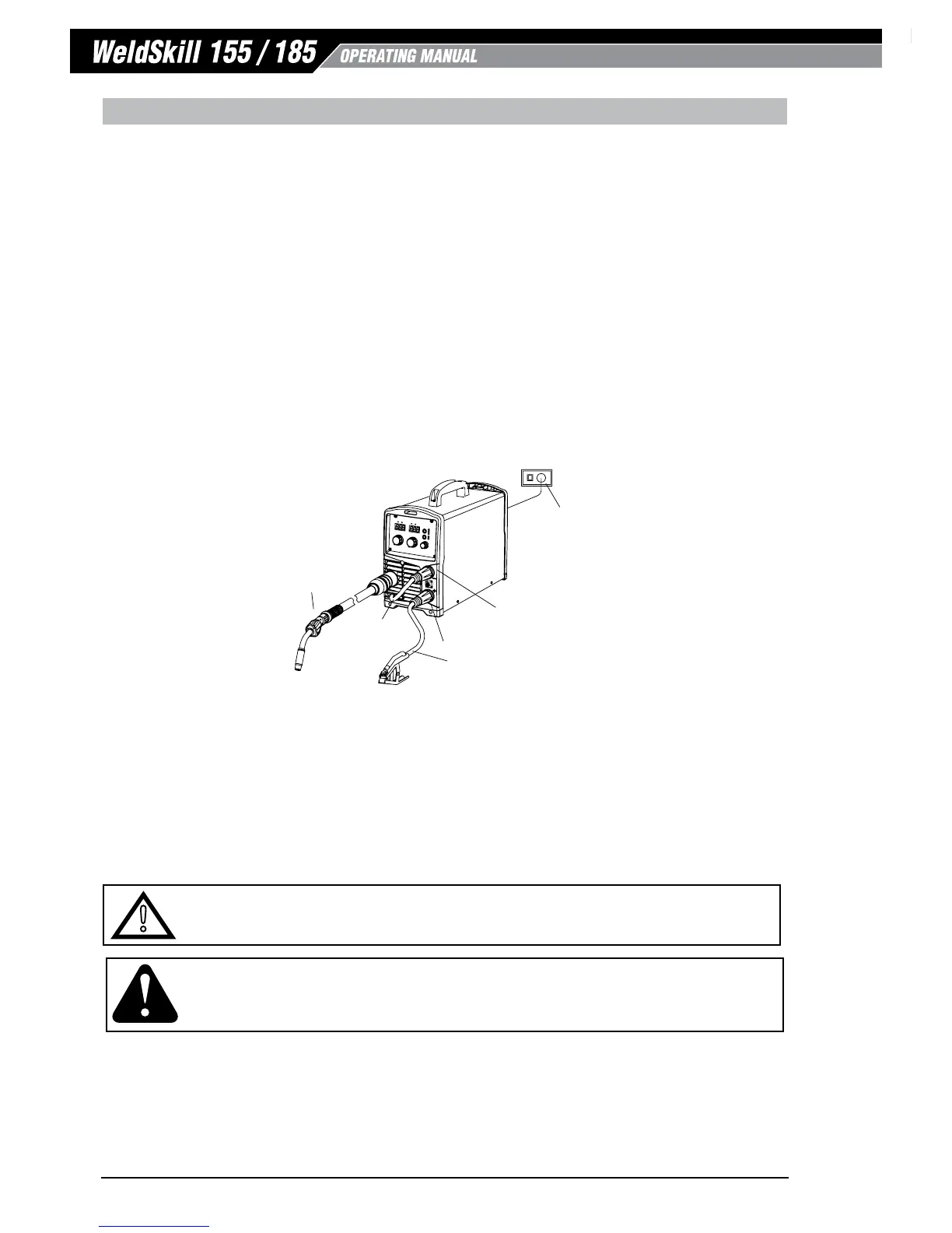
A. Fit the MIG Torch to the Power Source. (Refer to section 5.02 Attaching the MIG Torch).
B. Connect the Mig Torch polarity lead to the negative welding terminal (-). If in doubt, consult the wire
manufacturer. Welding current flows from the power source via Dinse terminals. It is essential, however,
that the male plug is inserted and turned securely to achieve a sound electrical connection.
C. Switch the Power Source On/Off switch (refer 4.02.18) located on the rear of the Power Source to the On
position and ensure the Power indicator on the Front Panel is illuminated. Set the MIG Torch trigger switch
operation either 2T ot 4T mode (WeldSkill 185 only). Refer to section 4.02.2.
D. Select MIG mode with the process selection control (refer to Section 4.02.1 for further information).
E. Fit the correct V Knurled Feed Roll for the Gasless MIG wire being used. Refer to section 2.11 Options and
Accessories for Feed Roll types and Part Numbers
F. Place the MIG wire spool onto the spool holder. Refer to sections 5.03 for 100mm diameter spools or 5.04
for 200mm diameter spools.
G. Feed wire through the wire drive mechanism. Refer to section 5.05.
Art # A-13449
MIG Torch
Negative Welding Terminal (-)
Positive Welding Terminal (+)
240VAC
10A
Mains Supply
MIG Polarity Lead
Work Lead
Figure 5-12: Setup for Mig Welding with Gasless Mig Wire
H. Connect the work lead to the positive welding terminal (+). If in doubt, consult the wire manufacturer.
Welding current flows from the power source via Dinse terminals. It is essential, however, that the male
plug is inserted and turned securely to achieve a sound electrical connection.
I. As a guide for the welding parameter settings for the welding job refer to the Weld Guide located on the
inside of the wirefeed compartment door. Power Source settings are adjusted using the front panel controls.
Refer to section 4.02.
!
WARNING
Before connecting the work clamp to the work piece make sure the mains power supply is switched o..
CAUTION
Loose welding terminal connections can cause overheating and result in the male plug being fused in the terminal.
Remove any packaging material prior to use. Do not block the air vents at the front or rear of the Welding Power Source.