Manual 0-5492 5-11 MIG (GMAW) WELDING
5.11 Setup for SPOOL GUN MIG (GMAW) Welding with Gas Shielded Mig Wire
(WeldSkill 185 Only)
A. Select MIG mode with the process selection control (refer to Section 4.02.01 for further information).
B. Connect the Mig torch polarity lead to the positive welding terminal (+). If in doubt, consult the wire
manufacturer. Welding current flows from the Power Source via Dinse type terminals. It is essential,
however, that the male plug is inserted and turned securely to achieve a sound electrical connection.
C. Fit the Euro Spool Gun to the power source using the front panel EURO torch adaptor (refer also to section
5.02 Attaching the Mig Gun). Connect the 8 pin Remote Control Plug to the 8 pin Remote Control Socket
on the power source. Ensure 8 pin plug is correctly fitted to the 8 pin socket on front panel and collar on
plug is tightened firmly.
D. Connect the work lead to the negative welding terminal (-). If in doubt, consult the wire manufacturer.
Welding current flows from the Power Source via Dinse type terminals. It is essential, however, that the
male plug is inserted and turned securely to achieve a sound electrical connection.
E. Fit the welding grade shielding gas regulator/flowmeter to the shielding gas cylinder (refer to Section 5.01)
then connect the shielding gas hose from the shielding gas regulator/flowmeter outlet to the quick connect
Shielding Gas Inlet fitting gas on the rear of the WeldSkill 185 Power Source. Ensure that the shielding gas
hose connection is sufficiently tight at the regulator connection and the quick connect fitting "locks" into
place correctly on the rear of the power source.
F. Refer to the Weld Guide located on the inside of the wirefeed compartment door for further information.
G. Select MIG mode with the process selection control (refer to section 4.02.01 for further information).
H. Set the Local/Remote Switch located inside the wire drive compartment, to Remote.
Art # A-13516
MIG Polarity Lead
Shielding Gas Cylinder
240VAC
10A
Mains Supply
Negative Welding Terminal
Positive Welding Terminal
Work Lead
Spool Gun
Remote Control Socket
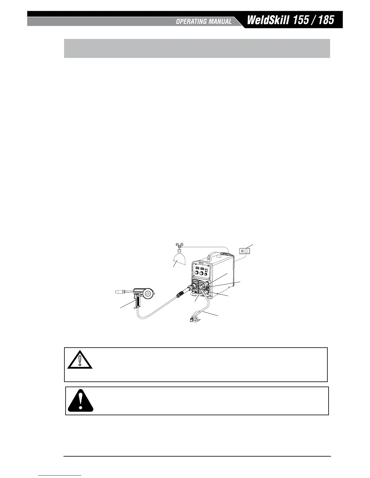
Figure 5-13: Setup for Spool Gun Welding with Gas Shielded Mig Wire with WeldSkill 185
!
WARNING
Before connecting the work clamp to the work piece make sure the mains power supply is switched o.
Secure the welding grade shielding gas cylinder in an upright position by chaining it to a suitable stationary support to
prevent falling or tipping.
CAUTION
Loose welding terminal connections can cause overheating and result in the male plug being fused in the terminal.
Remove any packaging material prior to use. Do not block the air vents at the front or rear of the Welding Power Source.