16
Installing the Electrolytic Cell and Flow Switch
The Cell and Flow Switch are to be fitted into the return line as the last pieces of equipment the water passes through
before returning to the pool: always after the pump, filter, heater (if applicable), etc. If a heater is present, all equipment
must be a minimum distance away, per heater manufacturer recommendations.
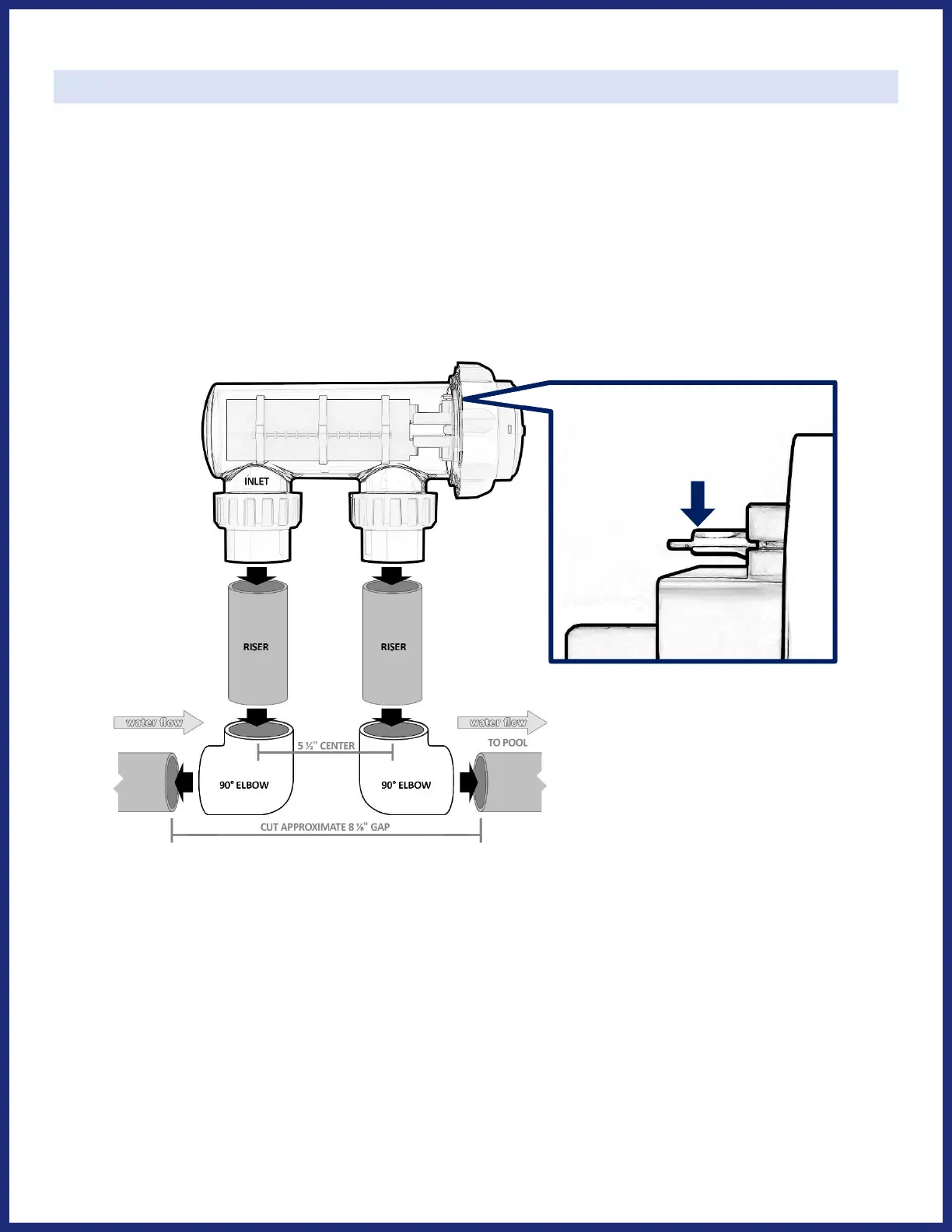
The Cell should be installed in the return line using two 90° elbows (not included) and two straight pieces of PVC pipe as
risers (not included). The Cell must be installed horizontally with ports facing down; as the highest point of the plumbing
this forms a natural gas trap, a secondary safety feature to prevent gas buildup in the system. When positioning the Cell,
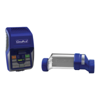
the inlet side of the Cell Housing is imprinted with an arrow pointing up. The Flow Switch can be installed horizontally or
vertically, in close proximity to the Cell; it is recommended to provide 6-10” of straight plumbing before the Flow Switch.
Ensure that the arrow on the Flow Switch faces in the correct direction of water flow. Lay out your equipment to ensure
adequate pipe space, and that the Cell cable (10’) can reach back to where the Control Panel will be installed.
1) After determining the section of plumbing to install the Cell, measure out and mark the selected area. Cut a gap in
the plumbing, so that you will be able to glue two 90° elbows on either side of the gap with a center-to-center
distance of 5 ½". Using standard 2” elbows, usually this gap is approximately 8 ⅛”.
2) Glue each 90° elbow to the end of each pipe stub on either side of the cut gap; ensure correct center-to-center
distance. TIP: dry-fit riser pieces into Housing, and use the ends of the risers as a guide to align 90° elbows.
3) Glue each riser into top of 90° elbows.
4) Glue Cell Housing assembly (including unions and collars) down onto risers, ensuring that Cell is level.
5) Ensure that all O-Rings are seated into their receiving channels in the Cell Housing. Slide the Cell into the Cell
Housing, making sure to carefully align the raised key on the plastic head of the Cell with the matching slot in the
clear Cell Housing. For a watertight seal, slide the Cell Cap into place and tighten it and the inlet/outlet ports by hand-
do not use tools or over-tighten, do not use lubricants on O-Ring