17
Installing the Control Module
Mount the Control Module as close to the pump and filtration system as possible. For safety concerns, do not install the
Control Module within 10 feet of the pool edges, and follow all applicable codes. Verify that the Cell cable can reach the
Control Module from the section of pipe selected for plumbing.
Using the mounting template as a guide, install screws at a comfortable level on a wall or vertical support, at least 3 feet
above ground level. Once the screws have been secured, align the holes on the back of the Control Module and mount to
the screws. The Module is fully rated for outdoor use; common sense considerations such as minimizing direct exposure to
rain, sunlight, water runoff, and lawn sprinkler systems will enhance longevity. As with most electronics, avoid placing the
controls in tightly enclosed spaces to avoid a build-up of excess heat. Do not mount above heater, if present.
TIP: Do not operate unit until all salt is dissolved in pool water and salinity is verified between 3000-4000 ppm.
Wiring
CAUTION: Power must be shut off at the circuit breaker before performing any wiring. Be sure to follow local and
NEC/CEC electrical codes. The system has been designed to easily wire into typical in-ground pool systems. To provide
safe operation, the unit must be properly grounded and bonded.
For operation, the Control Module must be wired into the pump's power source so that both turn on and off together
(see diagram on page 18). For variable speed pumps, use a timer to coordinate SJ run time with full-flow pump
operation.
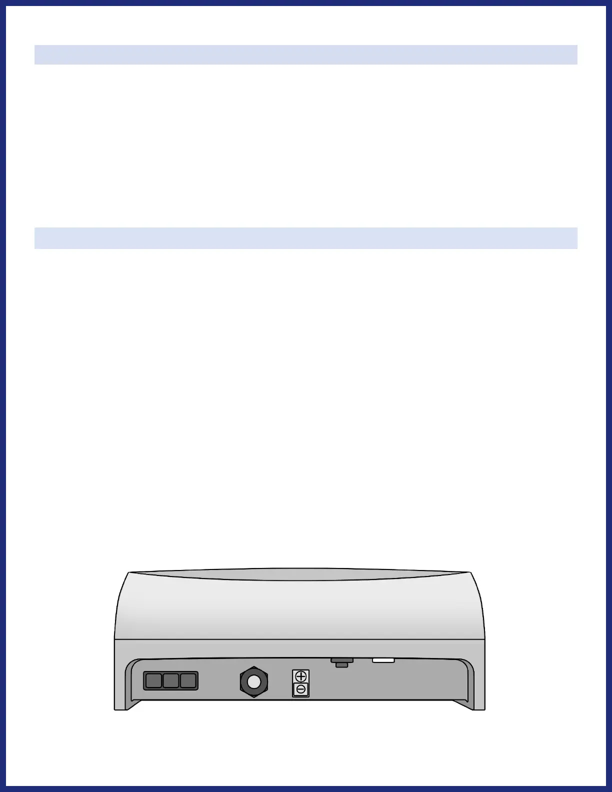
Electrolytic Cell Connection:
The Cell cable has a plug-in connector, which attaches easily to the Control Module. Press plug in firmly to ensure that
connector clicks in to place across the length of the plug. Refer to the diagram below for the location of these
connections.
Bonding:
A lug used for bonding is attached to the bottom of the SJ-Series Control Module. The Control Module must be bonded
with an 8 AWG bare copper wire to the pool bonding system.
Fuse Reset Button (Located on the inside vertical face):
For protection, the Fuse Reset will trip in the event of a power surge. If the power switch is in the On position, but the
controls are not illuminated, depress the rubber cover of the Fuse Reset Button until you feel a click.
Flow Switch Connection Port (Located on the inside vertical face):
Press the flow switch’s connector into the female port until you feel a click.