3�4�2�- TERMINALS ON THE LOWER FACE
21 22
23 24 25 26 27 28 29 30
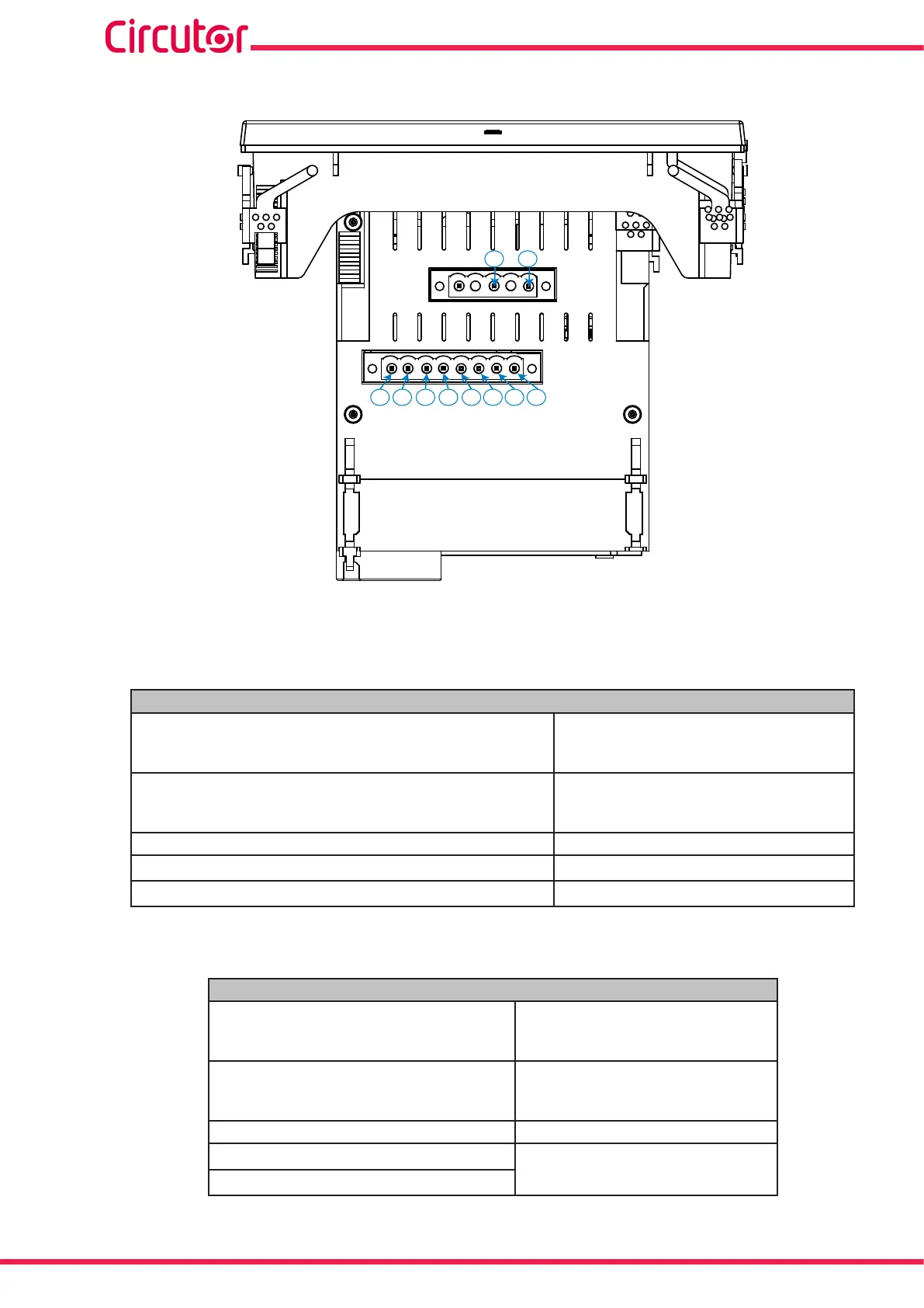
Figure 2:CVM-A terminals, lower face�
3�4�2�1�- CVM-A1x00-ITF Model
Table 7:List of terminals on the lower face of the CVM-A1x00-ITF�
Device terminals
21 : Auxiliary power supply.
~ +, CVM-Axxxx-ITF
-, CVM-Axxxx-ITF-SDC
26: S2, Current input L2
22: Auxiliary power supply.
~ -, CVM-Axxxx-ITF
+, CVM-Axxxx-ITF-SDC
27: S1
,
Current input L3
23: S1
,
Current input L1 28: S2, Current input L3
24: S2, Current input L1
29: S1, Neutral current input, LN
25: S1
,
Current input L2
30: S2, Neutral current input, LN
3�4�2�2�- CVM-A1x00-FLEX Model
Table 8:List of terminals on the lower face of the CVM-A1x00-FLEX�
Bornes del equipo
21 : Auxiliary power supply.
~ +, CVM-Axxxx-ITF
-, CVM-Axxxx-ITF-SDC
26: C2, Common for Current input L2
22: Auxiliary power supply.
~ -, CVM-Axxxx-ITF
+, CVM-Axxxx-ITF-SDC
27: L3
,
Current input L3
23: L1,
,
Current input L1 28: C3, Common for Current input L3
24: C1, Common for Current input L1
29, 30: SHLD, GND for current inputs
25: L2,
Current input L2
14
CVM-A1000 - CVM-A1500
Instruction Manual