Note: The maximum value must be greater than the minimum value programmed.
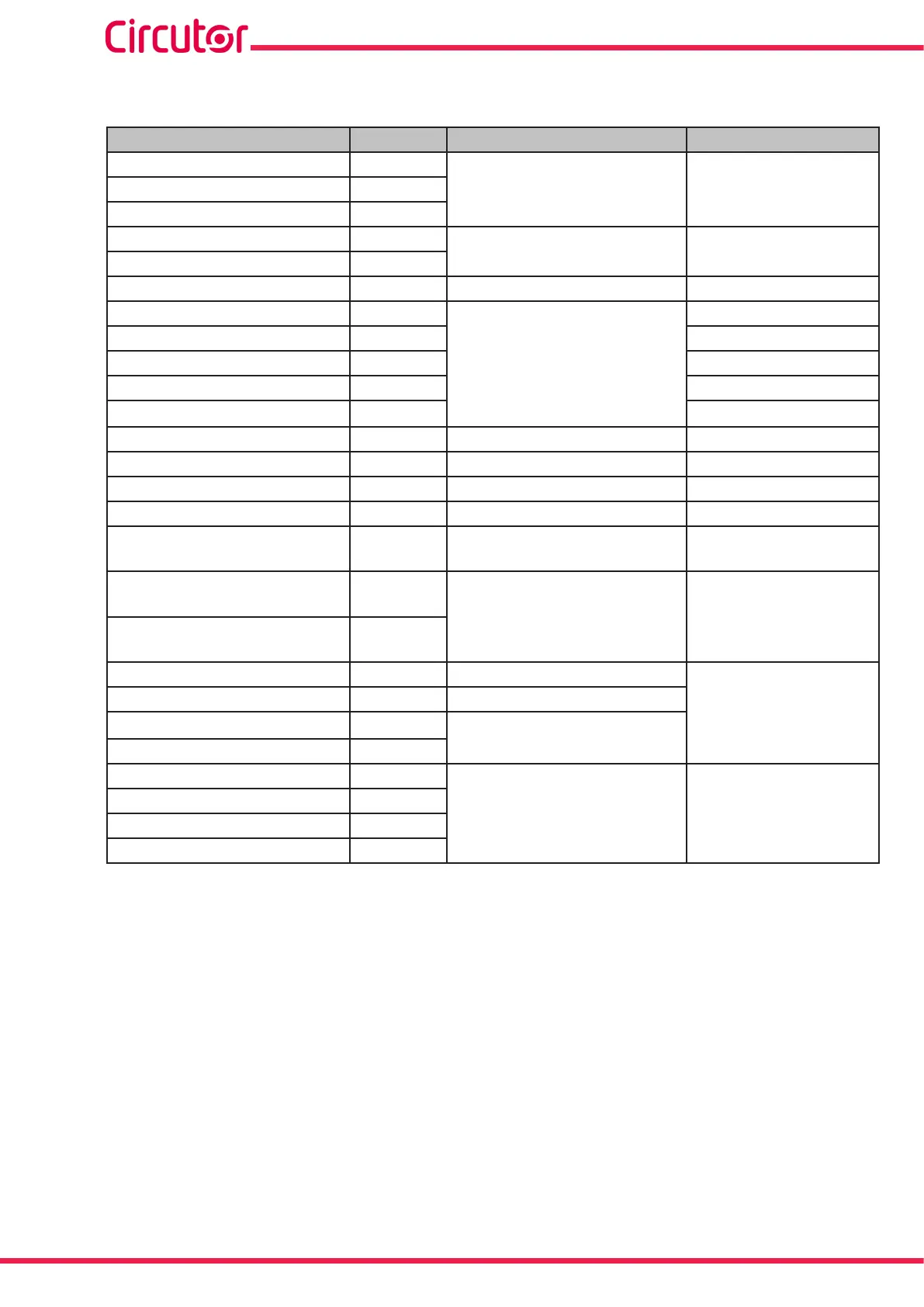
Table 34: Units and maximum and minimum values of the programming variables of the digital outputs�
Variable Units Maximum Minimum
Phase-Neutral Voltage V
1000.00 * voltage ratio
(28)
0Phase-Phase Voltage V
Neutral Voltage V
Current A
10.000 *current ratio
(29)
0
Neutral Current A
Frequency Hz 70.000 40.000
Active Power
(30)
kW
180000
-180000
Apparent Power
(30)
kVA 0
Total Reactive Power
(30)
kvar -180000
Inductive Reactive Power
(30)
kvar 0
Capacitive Reactive Power
(30)
kvar
0
Power factor - 1.00 -1.00
Cos φ º 1.00 -1.00
Voltage THD % % 100.0 0
Current THD % % 100.0 0
Maximum Demand of
Current
A 10.000 *current ratio
(29)
0
Maximum Demand of
Active power
kW
180000 0
Maximum Demand of
Apparent Power
kVA
PST Flicker (Pst) Pst 20.00
0.00
K-factor - 99.99
Voltage peak factor
-
20.00
Current peak factor -
% V Unbalance (Kd) -
100.000 0.000
% I Unbalance (Kd) -
% V Asymmetry(Ka) -
% I Asymmetry(ka) -
(28)
The voltage ratio is the ratio between the primary and secondary voltage.
(29)
The current ratio is the ratio between the primary and secondary current.
(30)
The three-phase powers accept up to 540000kW.
● When programming the connection delay (ON) of the relay digital output:
Maximum value: 999 s.
Minimum value: 0 s.
● When programming the disconnection delay (OFF) of the relay digital output:
Maximum value: 999 s.
Minimum value: 0 s.
● When programming the output status of the relay:
204
CVM-A1000 - CVM-A1500
Instruction Manual