50
ATM Line Card Installation and Configuration
OL-13004-01
Line Card Memory
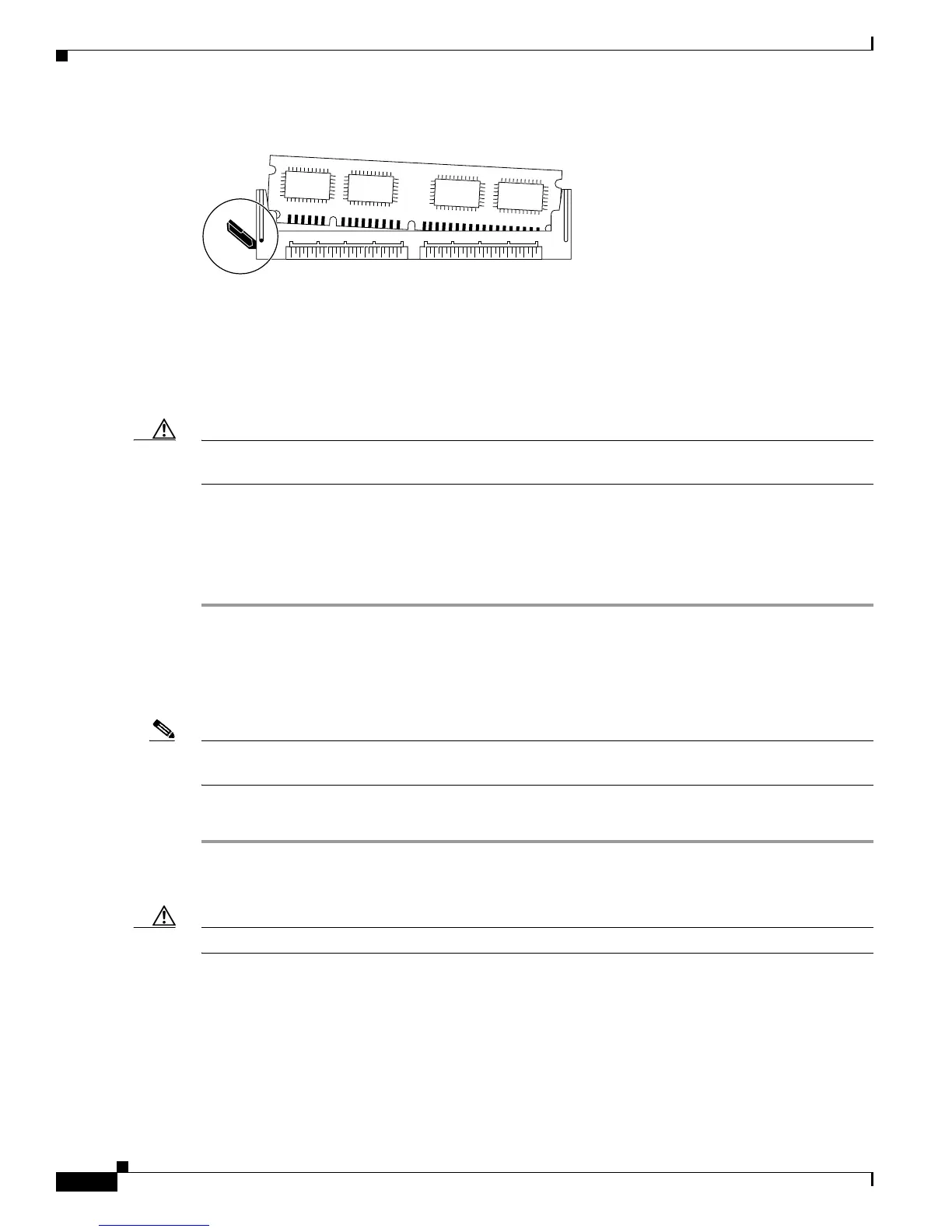
Figure 22 DIMM Socket with Single Release Lever
Step 4
Use the socket release levers to eject the DIMM.
• For a socket with dual release levers (see Figure 21), pull down both levers at the same time to eject
the DIMM.
or
• For a socket with a single release lever (see Figure 22), pull the lever to eject the DIMM.
Caution Handle the edges of the DIMM only. Do not touch the integrated circuit devices on the DIMM, the metal
traces, or fingers, along the edge of the DIMM, or the pins in the DIMM socket.
Step 5 As one end of the DIMM is released, grasp the top corners of the DIMM with the thumb and forefinger
of each hand and pull the DIMM completely out of its socket.
Step 6 Immediately place the DIMM in an antistatic bag to protect it from ESD damage.
Step 7 Repeat Step 4 through Step 6 for any remaining DIMMs that you want to remove.
Installing a DIMM
This section contains instructions for installing DIMM memory into a line card.
Note If you are upgrading packet memory, both DIMM sockets of a given pair (either the transmit buffer or
the receive buffer) must be populated with a DIMM of the same type and size.
To install DIMMs in a line card, follow these steps:
Step 1 Attach an ESD-preventive wrist or ankle strap and follow its instructions for use.
Step 2 Place the line card on an antistatic mat so that the faceplate is nearest to you.
Caution To prevent router and memory problems, all DIMMs installed in the line card must be 3.3V devices.
Step 3 Remove the new DIMM from its protective antistatic bag.
Step 4 Grasp the edges of the DIMM only. Do not touch the integrated circuit devices on the DIMM, the metal
traces, or fingers, along the edge of the DIMM, or the pins in the DIMM socket. (See Figure 23.)
Step 5 To position the DIMM for insertion, orient it at the same angle as the DIMM socket. The two notches
(keys) on the bottom edge of the module ensure that the DIMM edge connector is registered properly in
the socket. (See Figure 23.)
H6513

 Loading...