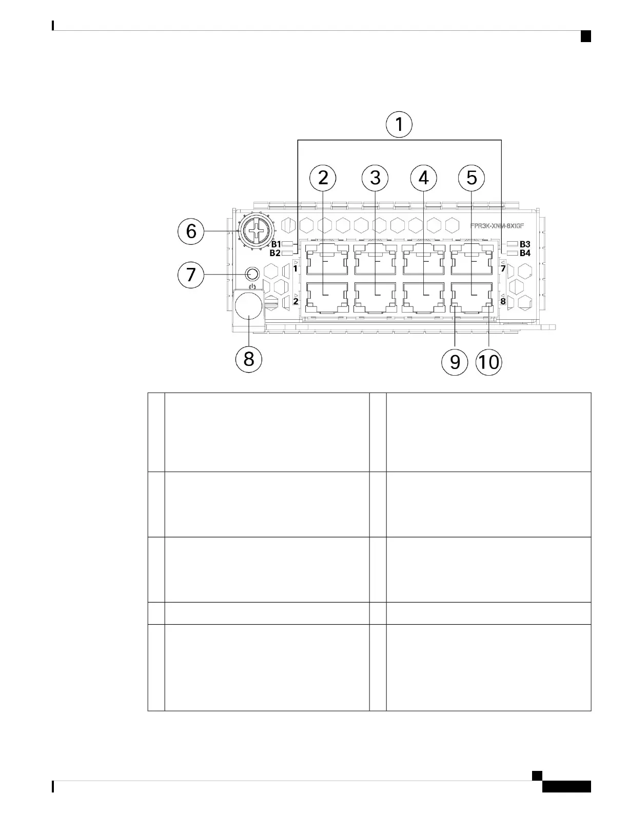
Figure 10: 10/100/1000Base-T Network Module
Ethernet X/1 and Ethernet X/2
Ports 1 and 2 are paired together to form a
hardware bypass pair. LED B1 applies to this
paired port.
2Bypass LEDs B1 through B4
• Green—In standby mode.
• Amber, flashing—Port is in hardware bypass
mode, failure event.
1
Ethernet X/5 and Ethernet X/6
Ports 5 and 6 are paired together to form a
hardware bypass pair. LED B3 applies to this
paired port.
4Ethernet X/3 and Ethernet X/4
Ports 3 and 4 are paired together to form a
hardware bypass pair. LED B2 applies to this
paired port.
3
Captive screw6Ethernet X/7 and Ethernet X/18
Ports 7 and 8 are paired together to form a
hardware bypass pair. LED B4 applies to this
paired port.
5
Handle8Power LED7
Right Port LED
• Unlit—No connection or port is not in use.
• Green—Link up.
• Green, flashing—Network activity.
10Left Port LED
• Unlit—No connection or port is not in use.
• Green—Link up.
9
Cisco Secure Firewall 3110, 3120, 3130, and 3140 Hardware Installation Guide
21
Overview
10/100/1000Base-T Network Module with Hardware Bypass
 Loading...