Power Supply Module LEDs
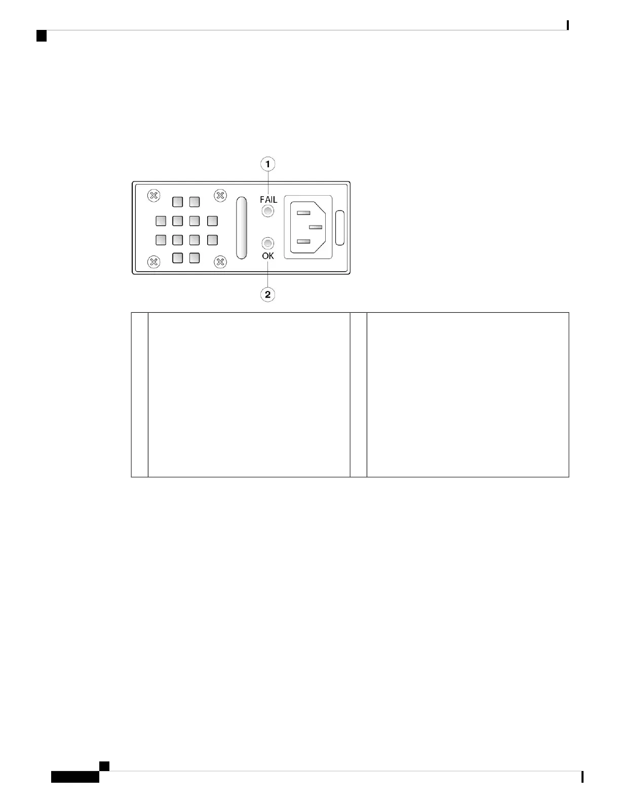
The following figure shows the bicolor power supply LEDs on the power supply module. The figure shows
the AC power supply module. The DC power supply module has the same LEDs.
Figure 12: Power Supply Module LEDs
Green OK LED
OK LED Status:
• Off—Input power not present.
• Green, flashing—Input power present, but
system is not powered up (power switch is
off).
• Green—The power supply module is enabled
and running.
2Amber FAIL LED
Fail LED Status:
• Off—No fault detected.
• Amber, flashing—Fault warning, power
supply may still work but could fail due to
high temperature, failing fan, or over current.
• Amber—Fault detected; power supply not
working properly. Includes over voltage,
over current, over temperature, and fan
failure.
1
For More Information
• See Remove and Replace the Power Supply Module, on page 71 for the procedure for removing and
replacing the power supply module in the Secure Firewall 3100.
Dual Fan Modules
The Secure Firewall 3100 has two dual fan modules that provide 3 + 1 redundancy. When one fan fails, the
other three spin at maximum speed so that the system continues to function. The dual fan modules are
hot-swappable and installed in the rear of the chassis.
The following figure shows the location of the fan LED on the fan module.
Cisco Secure Firewall 3110, 3120, 3130, and 3140 Hardware Installation Guide
26
Overview
Dual Fan Modules
 Loading...