If power is lost between when you pushed the reset button and when the reset process is complete, the
process stops and you have to push the button again after the system powers back on.
Note
For More Information
• See Remove and Replace the SSD, on page 67 for the procedure for removing a replacing the SSD.
• See Install, Remove, and Replace the Network Module, on page 65 for the procedure for installing
network modules.
• See 1/10/25-Gb Network Module, on page 15 for more information about the network module.
• See 1-Gb SX/10-Gb SR/10-Gb LR/25-Gb SR/25-Gb LR Network Module with Hardware Bypass, on
page 22 for more information about the network module.
• See 10/100/1000Base-T Network Module with Hardware Bypass, on page 20 for more information
about the network module.
• See 40-Gb Network Module, on page 17 for more information about the network module.
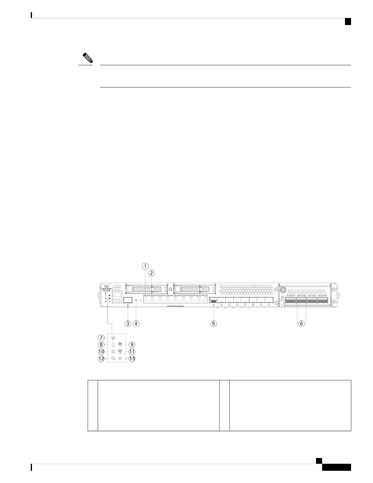
Front Panel LEDs
The following figure shows the Secure Firewall 3100 front panel LEDs.
Figure 6: Secure Firewall 3100 Front Panel LEDs
RJ-45 Copper Port Activity Status
• Off—No activity
• Green, flashing—The number of flashes
determines the link speed; 1 flash=10 Mb,
2=100 Mb, 3=1 Gb.
2RJ-45 Copper Port Link Status
• Off—No link.
• Green—Link is up.
1
Cisco Secure Firewall 3110, 3120, 3130, and 3140 Hardware Installation Guide
11
Overview
Front Panel LEDs
 Loading...