Step 4 Insert the exposed wire into the terminal block. Ensure that you cannot see any wire lead outside the plastic cover. Only
wires with insulation should extend from the terminal block.
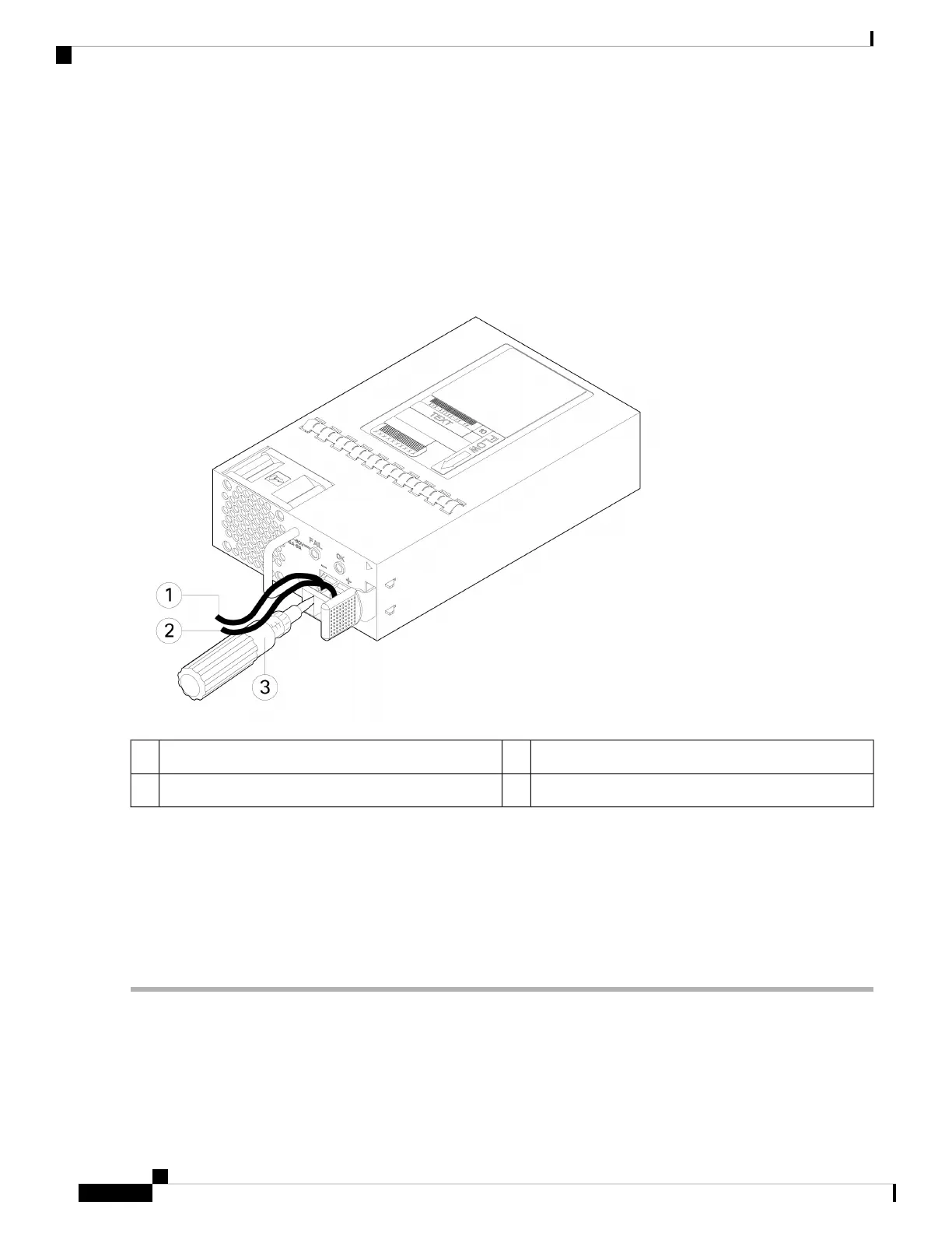
Step 5 Use a screwdriver to tighten the terminal block captive screws.
Do not over torque the terminal block captive screws. Make sure that the connection is snug, but the wire is
not crushed. Verify by tugging lightly on each wire to make sure that they do not move.
Caution
Figure 52: Tighten the Terminal Block Captive Screws
Positive (+) lead wire2Negative (-) lead wire1
—Screwdriver3
Step 6 Repeat these steps for the remaining DC input power source wire as applicable.
Step 7 Use a tie wrap so secure the wires to the rack, so that the wires are not pulled from the terminal block.
Step 8 Set the DC disconnect switch in the circuit to ON. In a system with multiple power supplies, connect each power supply
to a separate DC power source. In the event of a power source failure, if the second source is still available, it can maintain
system operation.
Step 9 Verify power supply operation by checking the power supply LED on the front of the chassis. See Front Panel LEDs, on
page 11 for the LED values.
Cisco Secure Firewall 3110, 3120, 3130, and 3140 Hardware Installation Guide
76
Installation, Maintenance, and Upgrade
Connect the DC Power Supply Module
 Loading...