16 500 Series Stackable Managed Switches
External Features of the Cisco 500
Series Stackable Managed Switch
This section describes the exterior of the switches including ports, LEDs,
and connectors.
Front Panel
The ports and LEDs are located on the front panel of the switch.
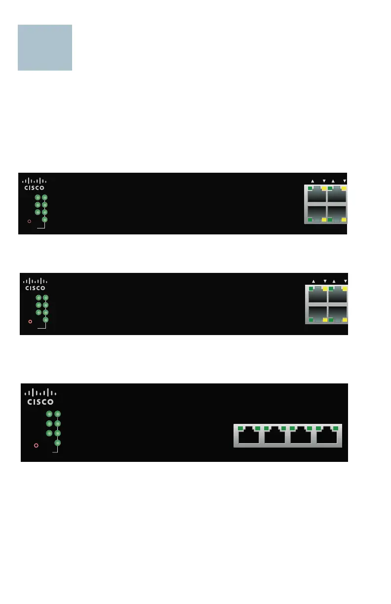
500X Left Side
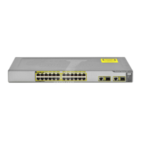
500 Left Side
SG500XG-8F8T Left Side
SG500X-24P 24-Port Gigabit with 4-Port 10-Gigabit PoE Stackable Managed Switch
1
1
2
3
4
13 2 14
PoE
LINK
ACT
Master
Fan
370001
System
Reset
Stack ID
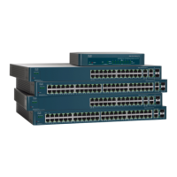
SG500-28P 28-Port Gigabit PoE Stackable Managed Switch
1
1
2
3
4
13 2 14
PoELINK
ACT
Master
Fan
370006
System
Reset
Stack ID
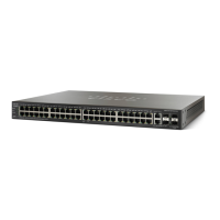
SG500XG-8F8T 16-Port 10-Gigabit Stackable Managed Switch
1
2
3
4
XG
12 34
LINK
ACT
Master
Fan
System
Reset
Stack ID
370008
 Loading...