3-10
Cisco ASA 5500 Series Hardware Installation Guide
78-17374-01
Chapter 3 ASA 5510, ASA 5520, ASA 5540, and ASA 5550
Installing the Chassis
b. Console port
–
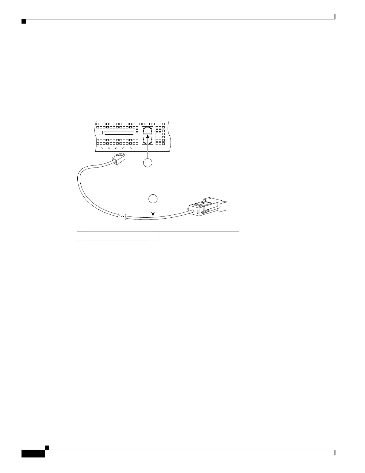
Connect the serial console cable as shown in Figure 3-10. The console cable has a DB-9
connector on one end for the serial port on your computer, and the other end is an RJ-45
connector.
–
Connect the RJ-45 connector to the Console port on the adaptive security appliance.
–
Connect the other end of the cable, the DB-9 connector, to the console port on your computer.
Figure 3-10 Connecting to the Console Cable
1 RJ-45 Console port 2 RJ-45 to DB-9 console cable
126982
FLASH
CONSOLE
AUX
POWER
STATUS
FLASH
VPN
ACTIVE
2
1

 Loading...