3-13
Cisco ASA 5500 Series Hardware Installation Guide
78-17374-01
Chapter 3 ASA 5510, ASA 5520, ASA 5540, and ASA 5550
Installing the Chassis
• SFP modules
–
Insert and slide the SFP module into the SFP port until you hear a click. The click indicates that
the SFP module is locked into the port.
–
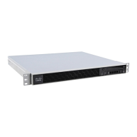
Remove the optical port plugs from the installed SFP as shown in Figure 3-13.
Figure 3-13 Removing the Optical Port Plug
–
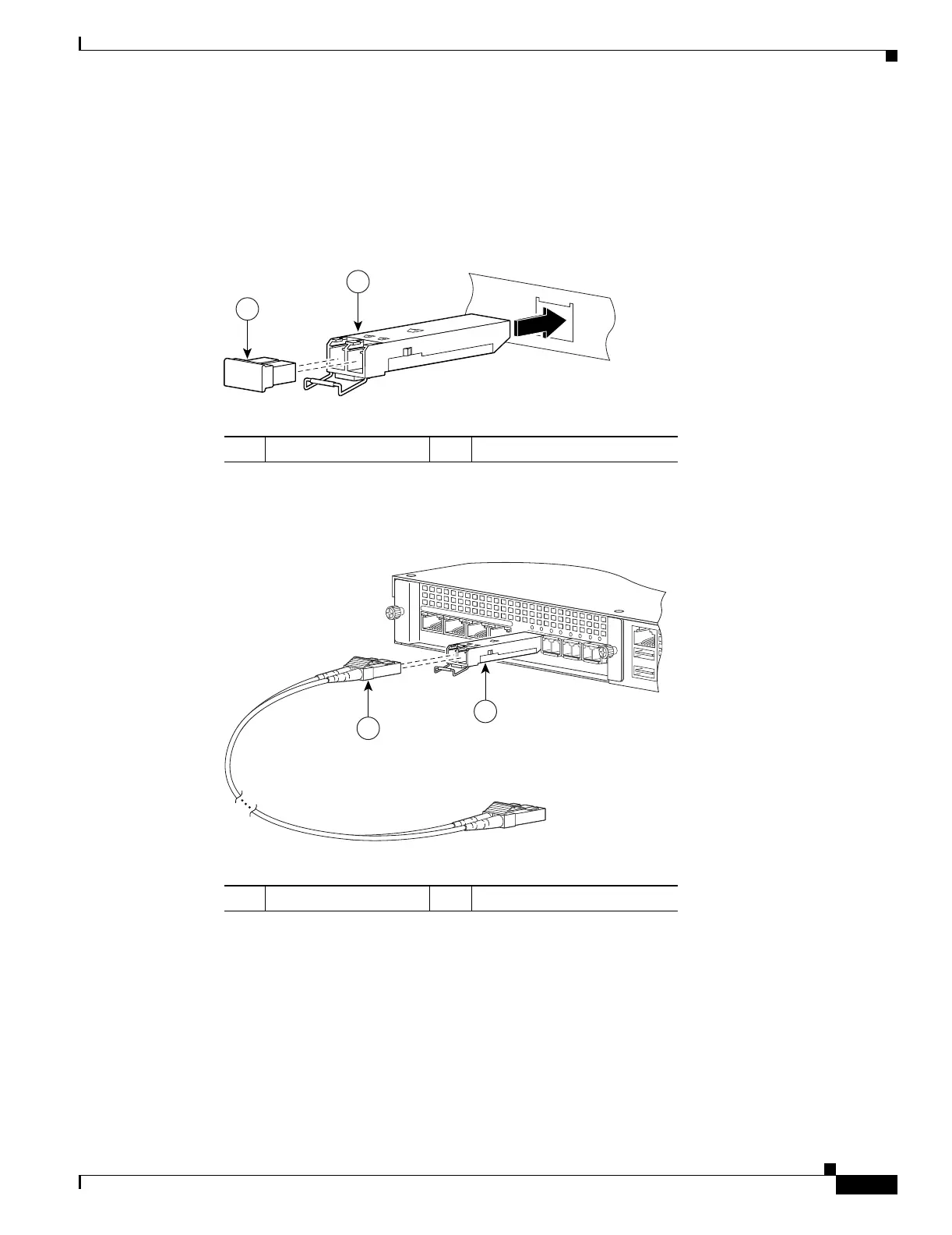
Connect the LC connector to the SFP module as shown in Figure 3-14.
Figure 3-14 Connecting the LC Connector
–
Connect the other end to your network devices, such as routers, switches, or hubs.
1 Optical port plug 2 SFP module
143146
1
STATUS
2
1 LC connector 2 SFP module
USB1
MGMT
USB2
MGMT
USB2
USB1
C
isco S
SM
-4G
E
LN
K
S
PD
0
123
POWER
S
T
A
T
U
S
1
143148
2

 Loading...