3-13
Cisco 7206 Installation and Configuration Guide
OL-5102-02
Chapter 3 Installing the Cisco 7206
Providing a Chassis Ground Connection for the Router Chassis
Use the following procedure to attach the grounding lug to the chassis grounding receptacles on your
router chassis:
Step 1 Locate the chassis grounding receptacles on your router chassis. (See Figure 3-11.)
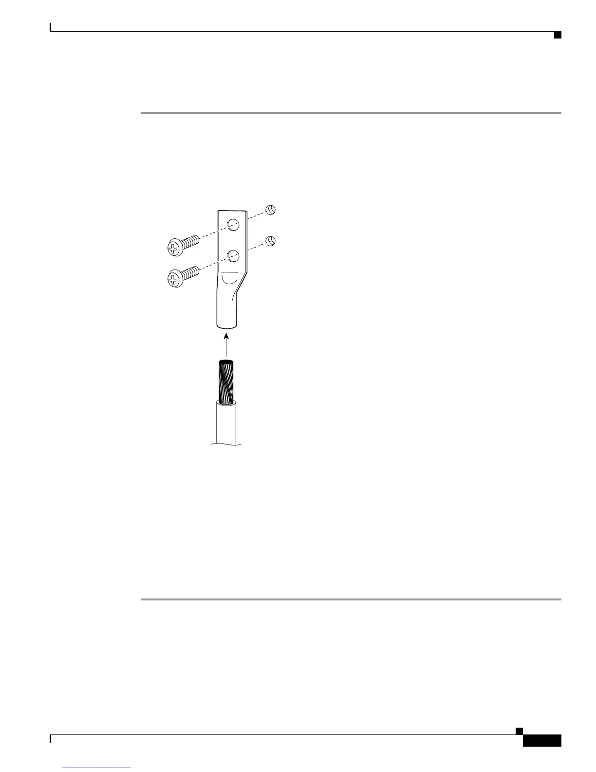
Step 2 Insert the two screws through the holes in the grounding lug. (See Figure 3-12.) Ensure that the
grounding lug does not interfere with other router hardware, such as power supplies or the network
processing engine.
Figure 3-12 Attaching a Grounding Lug to the Chassis Grounding Receptacles
Step 3
Use the Phillips screwdriver to carefully tighten the screws until the grounding lug is held firmly to the
chassis. Do not overtighten the screws.
Step 4 Use the wire stripper to strip one end of the 6-AWG wire approximately 0.75 inches (19.05 mm).
Step 5 Insert the 6-AWG wire into the wire receptacle on the grounding lug. (See Figure 3-12.)
Step 6 Use the crimping tool to carefully crimp the wire receptacle around the wire; this step is required to
ensure a proper mechanical connection.
Step 7 Connect the opposite end of the grounding wire to the appropriate grounding point at your site to ensure
an adequate chassis ground.
This completes the procedure for providing a chassis ground connection.
H10749
Grounding lug
Wire
Chassis
grounding
receptacles
Screws

 Loading...


