3-21
Cisco 7206 Installation and Configuration Guide
OL-5102-02
Chapter 3 Installing the Cisco 7206
Connecting Power
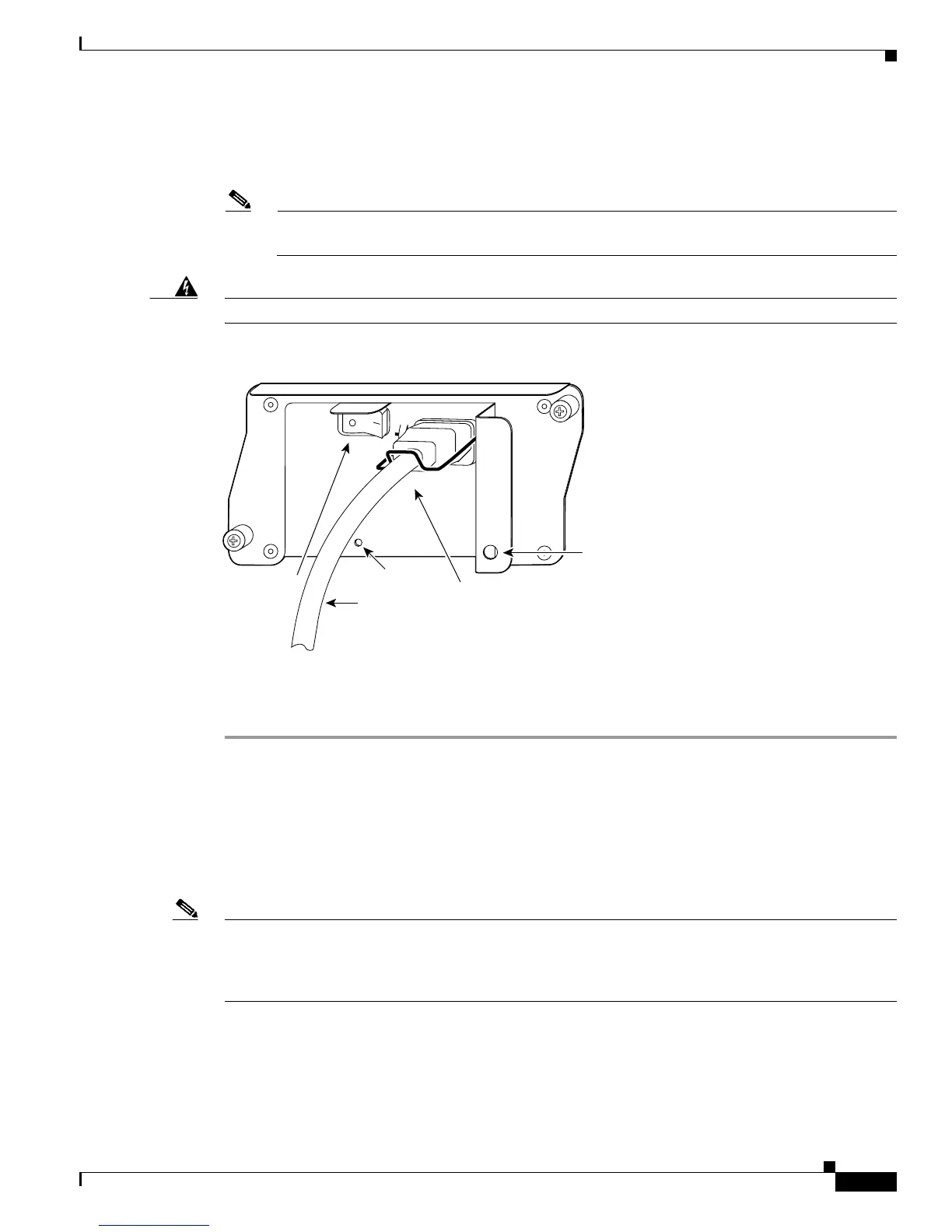
Step 3 Secure the cable in the power supply AC receptacle by sliding the cable-retention clip down until it fits
around the connector. The cable-retention clip provides strain relief for the AC power cable (refer to
Figure 3-21).
Note For additional AC power cable strain relief, secure the cable to the power supply handle by
inserting a nylon cable tie through the hole in the handle and around the cable.
Warning
The AC power supply for the Cisco 7206 has double pole/neutral fusing.
Figure 3-21 Connecting AC-Input Power
Step 4
Plug the AC power supply cable into the AC power source.
Step 5 Repeat Step 1 through Step 4 for the second power supply (if present).
This completes the procedure for connecting AC-input power.
Connecting DC-Input Power
Connect a 280W DC-input power supply as follows:
Note The color coding of the DC-input power supply leads depends on the color coding of the DC power
source at your site. Typically, green or green/yellow is used for ground. Make certain the lead color
coding you choose for the DC-input power supply matches lead color coding used at the DC power
source.
H6848
AC power cable
Cable-retention
clip
Hole for nylon
cable tie
Power switch
PWR OK LED

 Loading...


