3-22
Cisco 7206 Installation and Configuration Guide
OL-5102-02
Chapter 3 Installing the Cisco 7206
Connecting Power
Warning
Before completing any of the following steps, and to prevent short-circuit or shock hazards, ensure
that power is removed from the DC circuit. To ensure that all power is OFF, locate the circuit breaker
on the panel board that services the DC circuit, switch the circuit breaker to the OFF position, and
tape the switch handle of the circuit breaker in the OFF position.
Warning
When you install the unit, the ground connection must always be made first and disconnected last.
Step 1 Ensure that no current is flowing through the DC power supply leads. To ensure that all power is OFF,
locate the circuit breaker on the panel board that services the DC circuit, switch the circuit breaker to
the OFF position, and tape the switch handle of the circuit breaker in the OFF position.
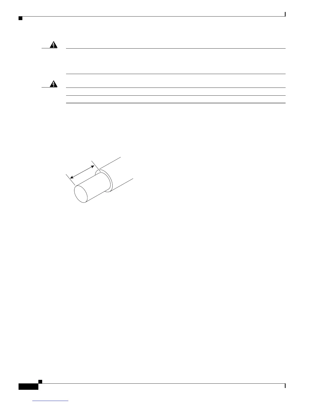
Step 2 Using a wire stripper, strip approximately 0.55 inch (14 mm) from the –V, +V, and ground leads (refer
to Figure 3-22).
Figure 3-22 Stripping the DC-Input Leads
Step 3
At the rear of the router, check that the power switch on the power supply is in the off (O) position (refer
to Figure 3-23).
Step 4 Insert the stripped end of the ground lead all the way into the ground lead receptacle on the DC-input
power supply and tighten the receptacle screw using a 3/16-inch flat-blade screwdriver (refer to
Figure 3-23).
0.55 in.
(14 mm)
H8624

 Loading...


