3-16
Cisco 7206 Installation and Configuration Guide
OL-5102-02
Chapter 3 Installing the Cisco 7206
Connecting I/O Controller Cables
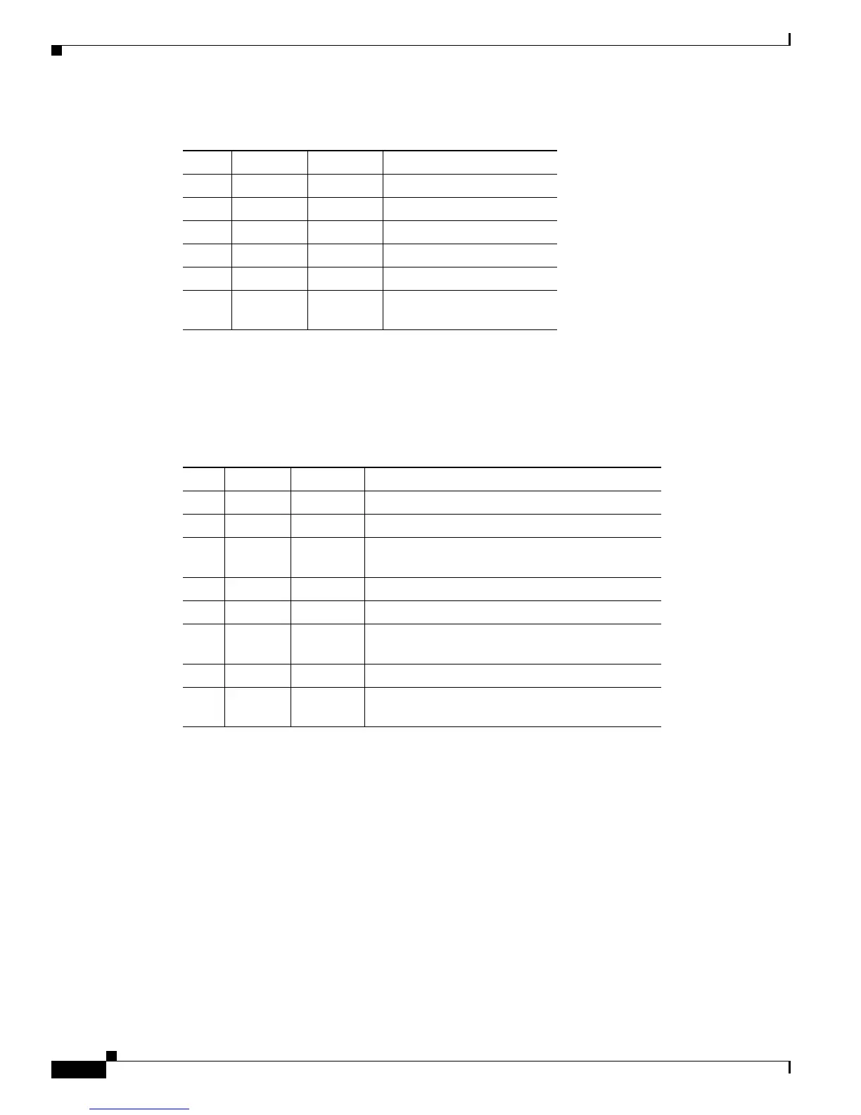
Auxiliary Port Signals
Table 3-2 lists the signals used on the auxiliary port. The auxiliary port supports hardware flow control
and modem control.
Fast Ethernet Connection Equipment
The I/O controller is available with or without a Fast Ethernet port. The I/O controller with a Fast
Ethernet port is equipped with either a single MII port or an MII port and an RJ-45 port (only one port
can be used at a time). Although still supported by Cisco Systems, the I/O controller equipped with the
single MII port was discontinued as an orderable product in May 1998. The following sections explain
Fast Ethernet MII and RJ-45 connection equipment.
Table 3-1 Console Port Signals
Pin Signal Direction Description
1 GND – Ground
2TxD <— Transmit Data
3RxD —> Receive Data
6DSR —> Data Set Ready (always on)
7 GND – Ground
8DCD —> Data Carrier Detect (always
on)
Table 3-2 Auxiliary Port Signals
Pin Signal Direction Description
2TxD —> Transmit Data
3RxD <— Receive Data
4RTS —> Request To Send (used for hardware flow
control)
5CTS <— Clear To Send (used for hardware flow control)
6DSR <— Data Set Ready
7 Signal
Ground
– Signal Ground
8CD <— Carrier Detect (used for modem control)
20 DTR —> Data Terminal Ready (used for modem control
only)

 Loading...


