3-31
Cisco 7200 VXR Installation and Configuration Guide
OL-5013-09
Chapter 3 Installing a Cisco 7200 VXR Router
Connecting I/O Controller, NPE-G1, or NPE-G2 Cables
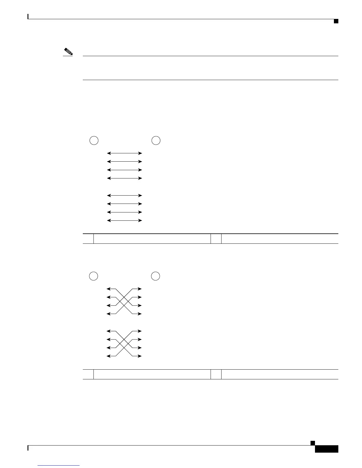
Note With reference to the RJ-45 pinout in Table 3-1, proper common-mode line terminations should be used
for the unused Category 5 UTP cable pairs 4/5 and 7/8. Common-mode line termination reduces
electromagnetic interference (EMI).
Depending on your RJ-45 interface cabling requirements, use the pinouts shown in Figure 3-21 and
Figure 3-22 for Gigabit Ethernet straight-through and crossover twisted-pair cable connections. Use
Figure 3-23 for Ethernet/Fast Ethernet straight-through and crossover twisted-pair cable connections.
Figure 3-21 Four Twisted-Pair Straight-Through Cable Pinouts for 10/100/1000 and 1000BASET
GBIC Module Ports
Figure 3-22 Four Twisted-Pair Crossover Cable Pinouts for 10/100/1000 and 1000BASET GBIC
Module Ports
1 Router 2 Hub
 Loading...