2-22
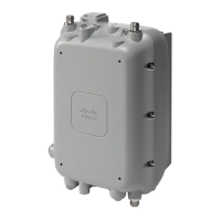
Cisco Aironet 1530 Series Outdoor Access Point Hardware Installation Guide
OL-30864-01
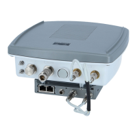
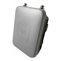
Chapter 2 Installing the Access Point
Mounting the Access Point
To mount the access point onto a vertical pole or streetlight pole, follow these steps:
Step 1 Select a mounting location on the pole to mount the access point. You can attach the access point to any
pole with a diameter from 2 to 8 inches (5.1 to 40.6 cm).
Note If you will be using a streetlight power tap adapter, position the access point within 3 ft (1 m) of the
outdoor light control.
Step 2 Mount the pivot bracket base to the pole using either one set of the adjustable band clamps or the screw
clamp (the screw clamp can be used on a pole that is not more than 3 inches in diameter).
Step 3 Position the pole clamp bracket on the pole as needed before tightening the metal bands. Tighten the
metal bands only enough to hold the bracket base in place, from sliding along the pole. Fully tighten the
bands only after the access point is positioned.
Step 4 Match the holes in the bracket plate to the holes in the back of the access point.
Step 5 Screw an M8 x12 mm bolt into each of the four bolt holes (using a 10 mm box wrench or socket, torque
the bolts to 40 lbf-in) on the back side of the access point and mounting bracket. (See Figure 2-11)
Note The access point should be positioned with the LEDs on the bottom to allow viewing from the ground.
Step 6 Mount the bracket with the AP, to the bracket on the pole. Use the long screw for this, as shown in the
exploded view – see Figure 2-11.
Step 7 Point the AP in the general desired position and tighten bolt, and then tighten the clamps on the pole.
The AP can be repositioned to its final position by loosening and re-tightening the bolts.
Crimping tool for ground lug, Panduit CT0720 with
CD-720-1 die (http://www.panduit.com)
No
Four wall mounting screws (6mm max) No
Four wall anchors (specified for all material) No
Drill bit for wall anchors No
Electric drill and standard screwdriver No
#6 AWG ground wire No
Shielded outdoor-rated Ethernet (CAT5e or better) cable No
Grounding block No
Grounding rod No
13-mm box-end wrench or socket set No
10-mm box-end wrench No
Materials Required In Kit
 Loading...