Negative lead10Fan5
The following table describes the LEDs on the Cisco ASR 1002-X Router –48 VDC power supply.
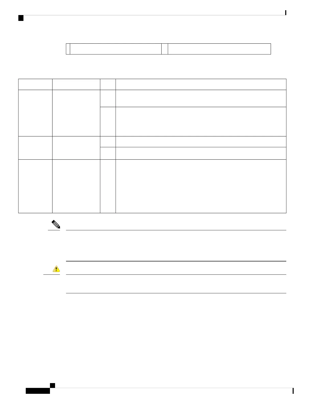
Table 10: Cisco ASR 1002-X Router –48 VDC Power Supply LEDs
DescriptionColorLEDLED Label
LED turns green to signal that the –48 VDC power supply input voltage is greater
than 43.5VDC at start and remains green down to 39VDC.
GreenA bi-color LED
indicates the presence
of input voltage
INPUT OK
The LED turns amber if the power supply turns off due to low input voltage (falls
below 39VDC) and indicates that there is still a hazard present (voltage on the
terminal block). The LED remains amber and is active till around 20 V +/-5 V. The
LED is not illuminated if the input is below 15 V.
Amber
The LED turns s green when all the fans are operational.Green
A bi-color LED
indicates power
supply fan status
FAN OK
The LED turns red when a fan failure is detected.Red
When the LED is off, it signals that the –48 VDC output voltage is within the normal
operating range. Output voltage between the minimum and maximum limits will
not create an output fail alarm, and output voltages below the minimum or above
the maximum will create an output fail alarm.
The Led turns red to indicate that the –48 VDC output is out of the specified range.
When you turn the power supply on, the LED turns red for 2 to 3 seconds to test
the LED operation before going off.
Red
Power supply activityOUTPUT
FAIL
The color coding of the –48 VDC input power supply leads depends on the color coding of the –48 VDC
power source at your site. Typically, green or green/yellow is used for ground. Ensure the lead color coding
you choose for the –48 VDC input power supply matches the LED color coding used at the –48 VDC power
source.
Note
When you install the unit, the ground connection must always be made first and disconnected last. Statement
1046
Danger
This section describes how to connect the –48 VDC power supply in the Cisco ASR 1002-X Router:
SUMMARY STEPS
1. At the rear of the router, check that the power supply Standby switch is in the Standby (see Figure 24:
Cisco ASR 1002-X Router –48 VDC Power Supply Terminal Block Cable Connections, on page 35 )
position.
2. Ensure that the negative and positive leads are disconnected from the site power source.
3. Using a wire stripper, strip approximately 0.55 inch (1.39 cm) from the negative, positive, and ground
lead.
Cisco ASR 1002-X Router Overview and Installation
34
Cisco ASR 1002-X Router Overview and Installation
Connecting the –48 VDC Input Power to the Cisco ASR 1002-X Router
 Loading...


