Installation of the equipment must comply with local and national electrical codes. Statement 1074
Warning
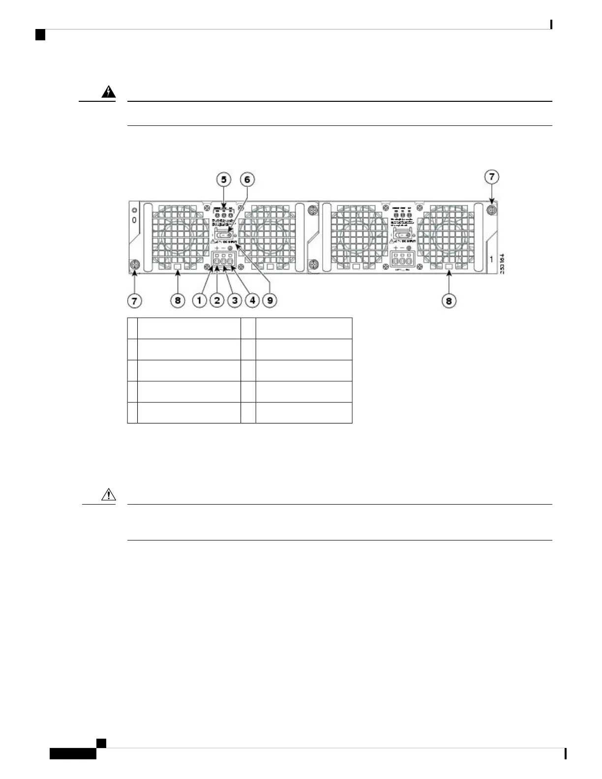
The following figure shows the +24 VDC power supply and components for the Cisco ASR 1002 Router.
Figure 58: Cisco ASR 1002 Router +24 VDC Power Supply
Standby/On switch6+24 VDC terminal block1
Captive fastener7Positive (+) lead2
Power supply tabs8Negative (-) lead3
+27 VDC INPUT label9Ground (GND) lead4
——Power supply LEDs5
Removing the +24 VDC Power Supply from Cisco ASR 1002 Router
Before you can remove a +24 VDC power supply from the Cisco ASR 1002 Router, you must remove input
power going to the power supply.
Make certain that the chassis ground lead wire is connected before you begin removing and installing the
power supply.
Caution
To remove the +24 VDC power supply from the Cisco ASR 1002 Router, follow these steps:
SUMMARY STEPS
1. Slip on the ESD-preventive wrist strap that was included in the accessory kit.
2. Place the power supply Standby switch in the Standby (see xref fig, item 6) position.
3. Using the recommended screwdriver, insert the screwdriver at an angle, pushing forward to release the
internal spring contact on the lead wire and then gently pull out the wire.
4. Remove screwdriver and continue removing the remaining lead wires from the terminal block, repeating
Step 4 through Step 5 for each lead wire.
5. Unscrew the two power supply captive screws.
6. Grasping the power supply handles, pull the power supply from the chassis.
Removing and Replacing FRUs from the Cisco ASR 1000 Series Routers
90
Removing and Replacing FRUs from the Cisco ASR 1000 Series Routers
Removing the +24 VDC Power Supply from Cisco ASR 1002 Router

 Loading...


