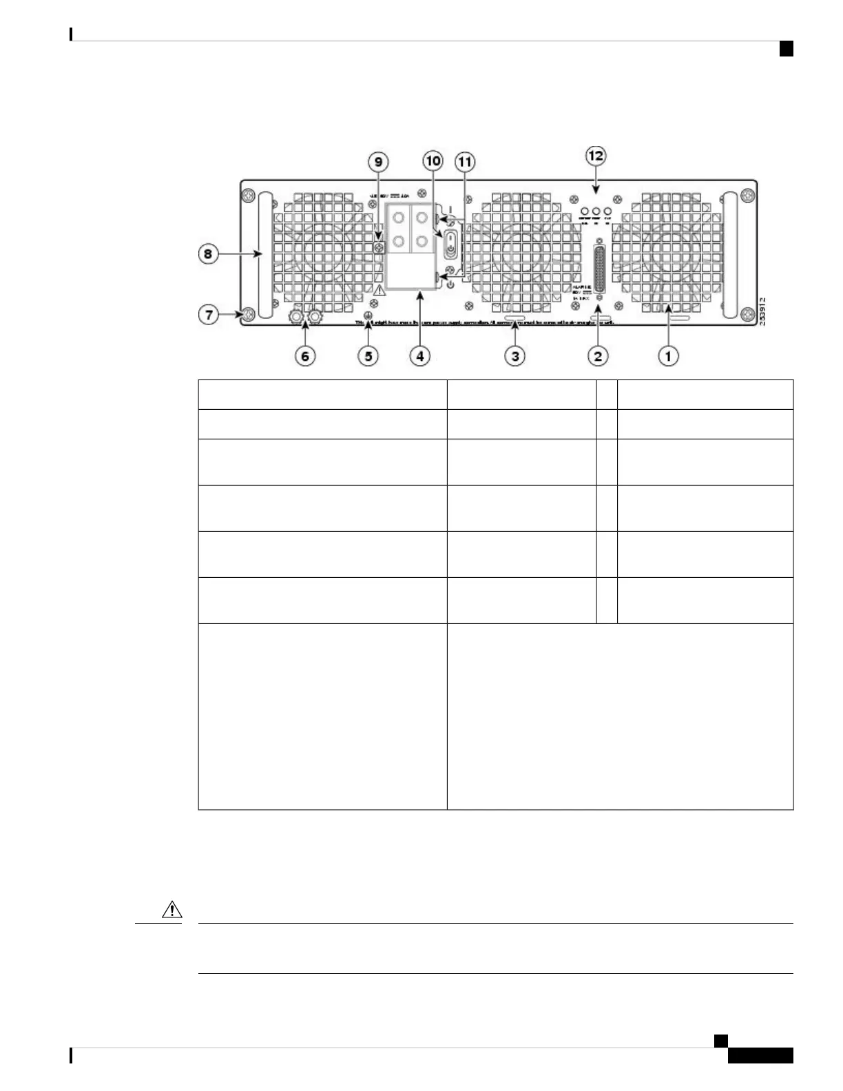
Figure 40: Cisco ASR 1006 Router DC Power Supply (ASR1013/06-PWR-DC)
DC power supply captive screw7Fan1
DC power supply handle8DB-25 alarm connector*2
Terminal block and plastic
cover single screw
9Tie-wrap tab3
On/Off (|/O) circuit breaker
switch
10DC power supply terminal
block and plastic cover
4
Terminal block and plastic
cover slot tab
11Ground symbol5
Power supply LEDs12DC power supply ground
studs
6
*For information about the DB-25 alarm
connector, how it works, and Cisco ASR
1000 route processor LEDs, see the xref
“How Cisco ASR1000-RP Alarm Monitoring
Works” section on page 2-20.
Note: Shielded cables must be used to
connect to the DB-25 alarm connector on
both the AC and DC power supplies, in order
to comply with FCC/EN55022/CISPR22
Class A emissions requirements.
Removing the DC Power Supply from Cisco ASR 1006 Router
Before you can remove a DC power supply from the Cisco ASR 1006 Router, you must remove power from
the power supply. Follow these steps to remove power and the DC power supply from the chassis.
Make certain that the chassis ground is connected before you begin removing and installing the power supply.
For the chassis ground stud location.
Caution
Removing and Replacing FRUs from the Cisco ASR 1000 Series Routers
63
Removing and Replacing FRUs from the Cisco ASR 1000 Series Routers
Removing the DC Power Supply from Cisco ASR 1006 Router

 Loading...


