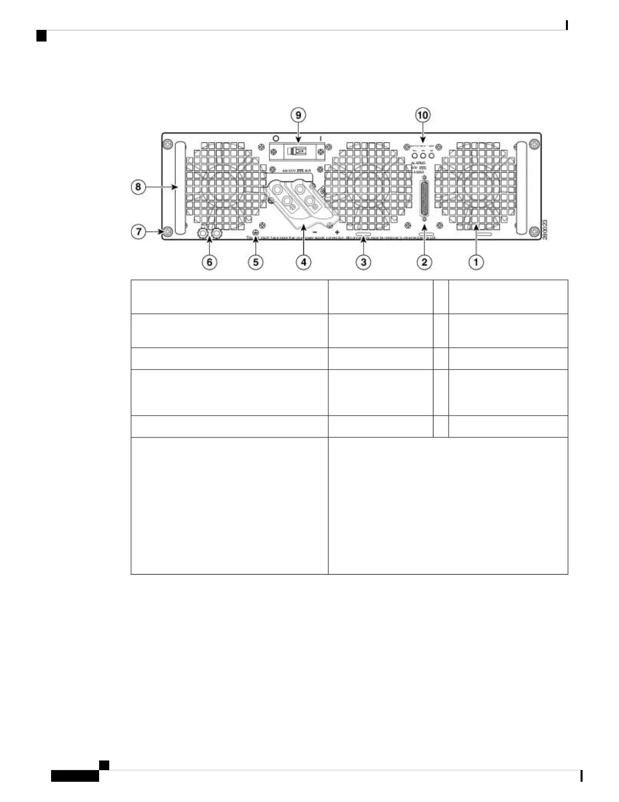
Figure 39: Cisco ASR 1006 Router DC Power Supply (ASR1006-PWR-DC)
DC power supply ground
studs
6Fan1
DC power supply captive
screw
7DB-25 alarm connector*2
DC power supply handle8Tie-wrap tab3
On/Off (|/O) circuit breaker
switch
9DC power supply
terminal block and
plastic cover
4
Power supply LEDs10Ground symbol5
*For information about the DB-25 alarm
connector, how it works, and Cisco ASR 1000
route processor LEDs, see the xref “How Cisco
ASR1000-RP Alarm Monitoring Works” section
on page 2-20.
Note: Shielded cables must be used to connect
to the DB-25 alarm connector on both the AC
and DC power supplies, in order to comply with
FCC/EN55022/CISPR22 Class A emissions
requirements.
The following figure shows the ASR1013/06-PWR-DC power supply and components.
Removing and Replacing FRUs from the Cisco ASR 1000 Series Routers
62
Removing and Replacing FRUs from the Cisco ASR 1000 Series Routers
Removing and Replacing a DC Power Supply in Cisco ASR 1006 Router
 Loading...


