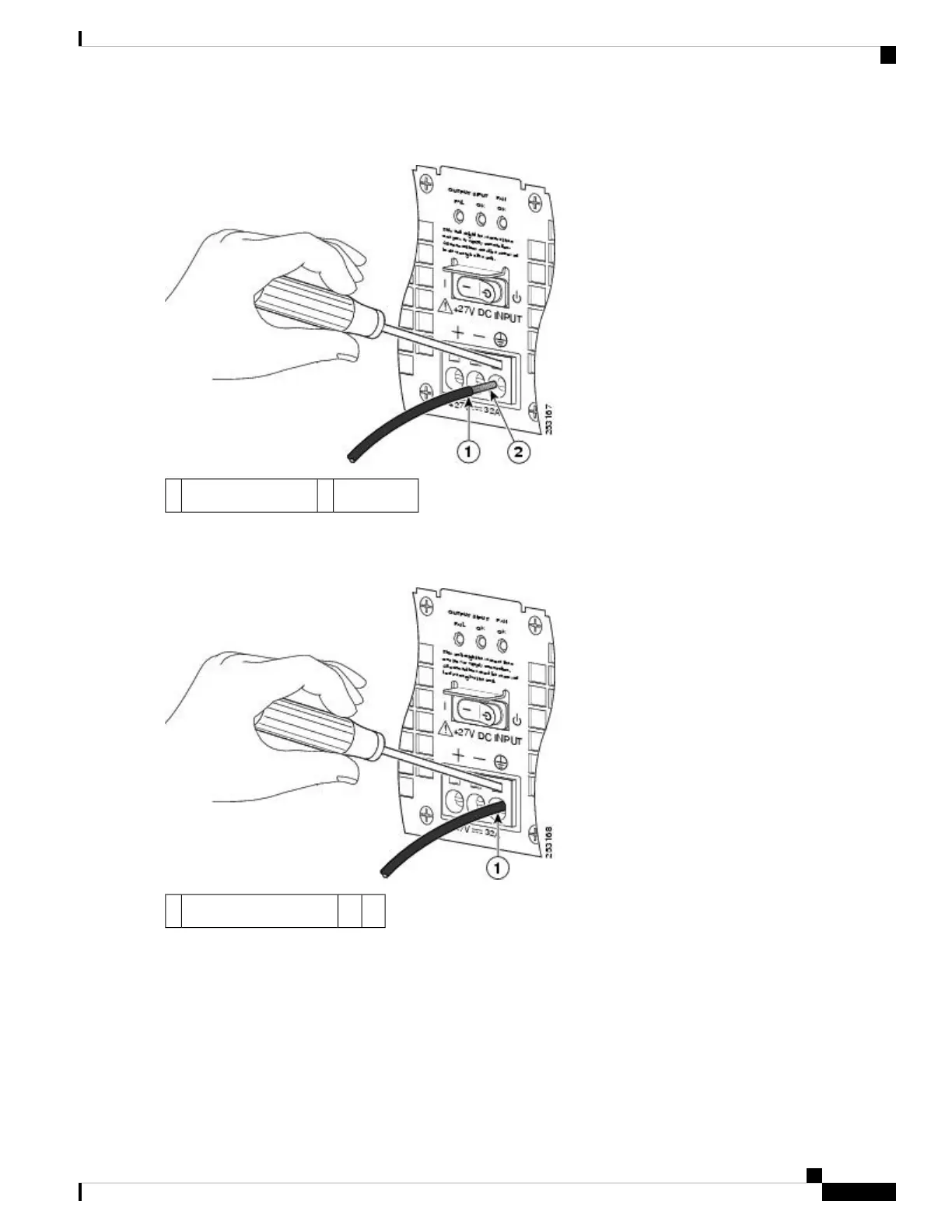
Figure 62: Cisco ASR 1002 Router +24 VDC Power Supply Lead Wire Inserted into the Terminal Block
Copper wire2Lead wire insulation1
Step 8 Make certain no copper wire is visible as shown in the following figure which shows the lead wire fully inserted.
Figure 63: Cisco ASR 1002 Router +24 VDC Power Supply Lead Wire Fully Inserted
——Fully-inserted lead wire1
Step 9 After the lead wire is fully inserted, hold the lead wire in place by pressing inward while you remove the screwdriver
to release the spring to tension down on the installed lead wire, then perform these steps:
a) Hold the lead wire in place while you are removing the screwdriver.
b) Once the screwdriver is completely removed, gently pull on the lead wire to make certain that the lead wire is
securely installed.
The following figure shows a lead wire fully inserted and the screwdriver removed while you gently pull on the
lead to make certain it is secured in the terminal block.
Removing and Replacing FRUs from the Cisco ASR 1000 Series Routers
95
Removing and Replacing FRUs from the Cisco ASR 1000 Series Routers
Replacing the +24 VDC Power Supply in Cisco ASR 1002 Router

 Loading...


