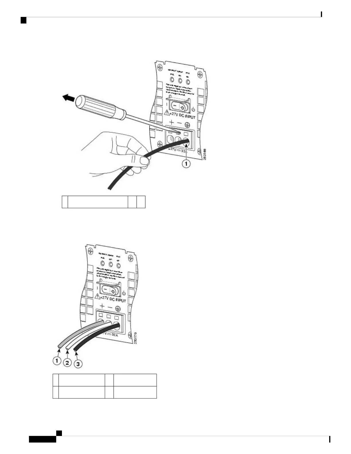
Figure 64: Removing a Screwdriver from the +24 VDC Power Supply Terminal Block
——Gently pull on lead wire.1
Step 10 Repeat Steps 5 through Step 10 for each lead wire. The following figure shows the leads wires installed in the terminal
block.
Figure 65: Cisco +24 VDC Power Supply Terminal Block with Lead Wires Installed
Ground lead wire3Positive lead wire1
——Negative lead wire2
Removing and Replacing FRUs from the Cisco ASR 1000 Series Routers
96
Removing and Replacing FRUs from the Cisco ASR 1000 Series Routers
Replacing the +24 VDC Power Supply in Cisco ASR 1002 Router
 Loading...


