2-69
Cisco ASR 9000 Series Aggregation Services Router Overview and Reference Guide
OL-17501-09
Chapter 2 Functional Description
Power System Functional Description
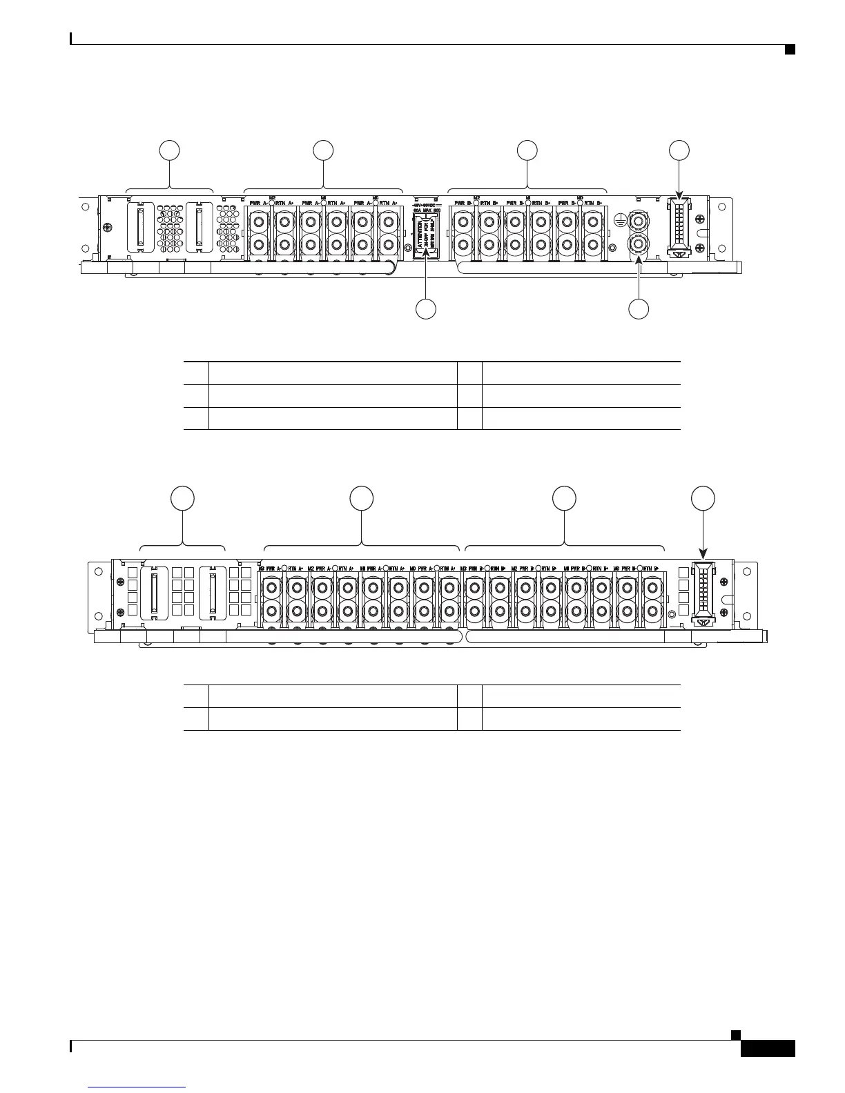
Figure 2-60 DC Power Tray Rear Panel
Figure 2-61 DC Power Tray Rear Panel - Cisco ASR 9006 Router and Cisco ASR 9904 Router with Version 2 Power System
DC Power Tray Power Feed Indicator
Figure 2-62 shows the location of the power feed indicators on the rear panel of the DC power tray for
the Cisco ASR 9010 Router and Cisco ASR 9006 Router with a version 1 power system. Figure 2-63
shows the location of the power feed indicators on the rear panel of the DC power tray for the
Cisco ASR 9006 Router and Cisco ASR 9904 Router with a version 2 power system.
1 DC output power blades 4 I2C cable from backplane
2 “A” feed connectors 5 Primary ground
3 “B” feed connectors 6 Power switch
1 DC output power blades 3 “B” feed connectors
2 “A” feed connectors 4 I2C cable from backplane
 Loading...


